


Abstract
Atherosclerosis underlies coronary artery disease, the leading cause of death in the United States and worldwide. Detection of coronary plaque inflammation remains challenging. In this study, we developed a scintillating balloon-enabled fiber-optic radionuclide imaging (SBRI) system to improve the sensitivity and resolution of plaque imaging using 18F-FDG, a marker of vascular inflammation, and tested it in a murine model. Methods: The fiber-optic system uses a Complementary Metal-Oxide Silicon (CMOS) camera with a distal ferrule terminated with a wide-angle lens. The novelty of this system is a scintillating balloon in the front of the wide-angle lens to image light from the decay of 18F-FDG emission signal. To identify the optimal scintillating materials with respect to resolution, we calculated the modulation transfer function of yttrium–aluminum–garnet doped with cerium, anthracene, and calcium fluoride doped with europium (CaF2:Eu) phosphors using an edge pattern and a thin-line optical phantom. The scintillating balloon was then fabricated from 10 mL of silicone RTV catalyst mixed with 1 mL of base and 50 mg of CaF2:Eu per mL. The addition of a lutetium oxyorthosilicate scintillating crystal (500 μm thick) to the balloon was also investigated. The SBRI system was tested in a murine atherosclerosis model: carotid-ligated mice (n = 5) were injected with 18F-FDG, followed by ex vivo imaging of the macrophage-rich carotid plaques and nonligated controls. Confirmatory imaging of carotid plaques and controls was also performed by an external optical imaging system and autoradiography. Results: Analyses of the different phosphors showed that CaF2:Eu enabled the best resolution of 1.2 μm. The SBRI system detected almost a 4-fold-higher radioluminescence signal from the ligated left carotid artery than the nonligated right carotid: 1.63 × 10² ± 4.01 × 101 vs. 4.21 × 101 ± 2.09 × 100 (photon counts), P = 0.006. We found no significant benefit to adding a scintillating crystal to the balloon: 1.65 × 10² ± 4.07 × 101 vs. 4.44 × 101 ± 2.17 × 100 (photon counts), P = 0.005. Both external optical imaging and autoradiography confirmed the high signal from the 18F-FDG in carotid plaques versus controls. Conclusion: This SBRI system provides high-resolution and sensitive detection of 18F-FDG uptake by murine atherosclerotic plaques.
According to the National Center for Health Statistics 2011 report, coronary artery disease (CAD) remains the leading cause of mortality in the United States in men and women of every major ethnic group. CAD claims more lives each year than the next 4 leading causes of death combined—cancer, chronic lower respiratory diseases, accidents, and diabetes mellitus (1). Disappointingly, CAD has recently become the world’s leading killer, overtaking even infectious diseases in the developing world.
Over the last several decades, basic cardiovascular research has significantly enhanced our understanding of pathobiologic processes leading to the formation, progression, and complications of atherosclerotic plaques (2). By harnessing these advances in cardiovascular biology, imaging has advanced beyond its traditional anatomic domains to a tool that permits probing of particular molecular structures to image cellular behavior and metabolic pathways involved in atherosclerosis (2). However, the current clinical paradigm for detecting CAD is angiography, which evaluates only the luminal encroachment of the disease, without providing information about plaque extent and content (3). Also, it has been shown that most plaques that cause acute coronary events are not hemodynamically significant (4). Although a wide range of molecular imaging modalities has been developed for detection and characterization of atherosclerosis in large vessels, detecting high-risk (i.e., vulnerable) plaques in the small, mobile coronary arteries remains a challenge (5–9).
Macrophage infiltration in atherosclerotic plaques plays an important role in the progression of atherosclerosis (10). Macrophage-rich inflammation is particularly intense in the high-risk plaques associated with acute coronary events and symptomatic carotid vascular disease (11–14). As a result, macrophages have become widely recognized as a key target for atherosclerosis imaging (15). Several studies have shown that 18F-FDG can be a marker of metabolically active high-risk plaques because of its uptake by inflammatory macrophages in the carotids and aorta (16–18). 18F-FDG PET imaging is based on the higher metabolic glucose demand of macrophages than their surrounding cells in the plaque; upregulated hexokinase increases radiolabeled glucose accumulation through glucose transporters (19). However, PET 18F-FDG detection in coronary plaque is still challenging because of the small size of such plaques, signal blurring due to motion, and obscuring 18F-FDG uptake by adjacent myocardium (20). Therefore, the advent of an intravascular molecular imaging approach has the potential to overcome these limitations by minimizing the distance and maximizing the sensitivity to coronary plaque signal.
Previously, we demonstrated the feasibility of a novel dual-modality fiber-optic system with an off-the-shelf scintillating screen (not attached to the system) (21) for plaque 18F-FDG detection. In this current study, we have fabricated and integrated a novel scintillating balloon for our fiber-optic imaging system to detect 18F-FDG–enriched atherosclerotic plaques, which may have the ability to image a 360° degree view of an artery. Therefore, the aims of this study were to develop this fiber-optic imaging system with a scintillating balloon to detect 18F-FDG glucose probe, characterize the system for spatial resolution from multiple scintillating materials, and validate the system on ex vivo macrophage-rich murine plaques with confirmatory external optical imaging and autoradiography.
MATERIALS AND METHODS
Scintillating Balloon Radionuclide Imaging (SBRI)
System Design
The optical components of the SBRI system were described in detail in a previous study by our research group (21). In brief, the system consists of a wide-angle lens (4.9 × 3.6 mm), providing a 180° degree view inside an artery, with a focal length of 3.85 mm, attached to the distal ferrule of a leached image fiber bundle (Fig. 1). The proximal end of the fiber bundle is connected to an 8-mm megapixel fixed-focal-length lens, and the other end of this lens is attached to a filter wheel. A 35-mm lens connects the filter wheel to a Complementary Metal-Oxide Silicon (CMOS) camera (NEO sCMOS; Andor Technology) and a computer. The novelty of the SBRI system is a scintillating balloon made from organic calcium fluoride doped with europium (CaF2:Eu) phosphor, placed in the front of the wide-angle lens to convert the β particles of the positron emission signal into visible light due to radioactive decay (primary decay time, 940 ns). The molecules in the scintillating balloon get excited with the incoming ionizing radiation, especially β particles from the decay of 18F-FDG by absorbing energy. When these molecules relax and return to a lower energy state from an excited state, they release optical radiation in the visible range. This light is then captured with the camera using deep thermoelectric cooling at −40°C for minimizing the background signal from the temperature-dependent dark current, hot pixel blemishes, and vibration. The exposure time was set to 10 s, which enabled sufficient signal from the ex vivo plaques. For 18F-FDG imaging with the SBRI system, the binning factor was set at small (4 × 4 pixels), with an active pixel size of 2,160 × 2,560 (width × height). The frame rate was set to 0.1 frames per second with an internal trigger mode. The SBRI system was placed in a light-tight black box during the ex vivo experiments to prevent ambient light. The selection process of optimal scintillating material and resolution of the balloon are described in the following sections.

Catheter-based SBRI system was housed in light-tight black box to remove ambient light. System was used to detect 18F-FDG uptake by vulnerable atherosclerotic plaque inside mouse carotid artery.
Optimal Phosphor
The scintillating balloon was fabricated from a membrane of CaF2:Eu phosphor (Saint-Gobain Crystals). To identify the optimal scintillating materials with respect to highest radioluminescence signal, several scintillating phosphors were tested. The scintillating membranes were made from 10 mL of Tap Silicone RTV catalyst (TAP Plastics, Inc.) with a medium viscosity of 60,000 cP, 1 mL of base, and 1 mL of dichloromethane anhydrous 99.9% acroseal (reduced viscosity of the solution to get a evenly smooth surface) mixed with 3 different concentrations (0.5, 5, and 50 mg/mL) of either yttrium aluminum garnet doped with cerium (YAG:Ce), anthracene, or CaF2:Eu phosphor with 3 different thicknesses (100, 150, 200 μm).
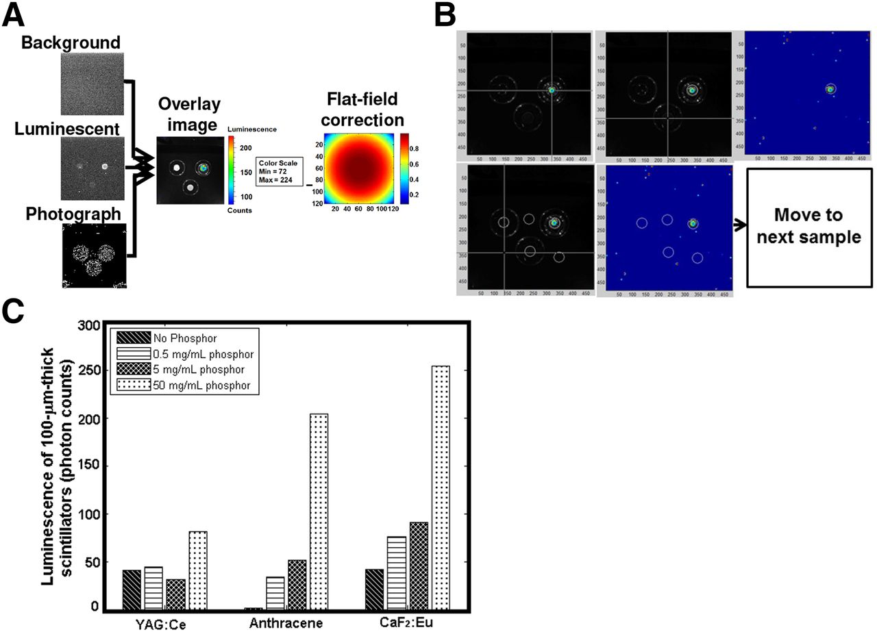
To identify the best phosphor, 3 different membranes (2 of them made with the same thickness/phosphor concentrations, but different phosphors, and 1 control membrane made with the same thickness with no phosphor) were placed on top of 3 β sources (204Tl, 3.7 kBq [0.1 μCi]). Three different images (background, luminescent, and white light photograph) were collected with the External Optical Imaging (IVIS-200) system (Xenogen Corp./Caliper Life Sciences) for each set of experiments. The highest radioluminescence signal intensity from the sample was identified from the images after the flat-field correction was applied for the specific camera used in the IVIS-200 system (Fig. 2A). A custom-written MATLAB (MathWorks) code was implemented to automatically extract the radioluminescence signal from the images (Fig. 2B).

Process of selecting the best scintillating phosphor. (A) Overlay image was created from 3 different images—background, luminescent, and photograph after correction for field flatness, which was specific to camera used in the IVIS-200 imaging system. (B) Radioluminescence signal extraction process. (C) Radioluminescence signal intensity from scintillating membranes made with 3 different phosphors. Max = maximum; min = minimum.
Resolution Analysis
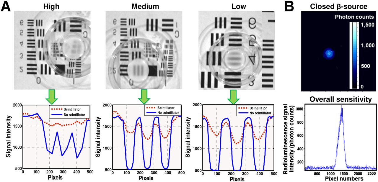
The resolution of the scintillating balloon was calculated using the modulation transfer function (MTF) of an edge pattern (Fig. 3) and tilted thin-line optical phantoms (Fig. 4). MTF is an important aid to objective evaluation of the image-forming capability of the scintillating balloon, providing a means of expressing the imaging quality of the optical system objectively and quantitatively as well as predicting performance reliably (22). Each scintillating membrane (mentioned in the “Optimal Phosphor” section) was placed on top of a pattern (classified as high, medium, or low resolution), or a tiled thin line, and imaged with a ProEM charge-coupled device (CCD) camera attached to an IVIS-200 system. A custom-written MATLAB algorithm was used to characterize the line profile. The MTF algorithm for the tiled thin line encompassed calculation of slope, up-sampling 10×, correction offset, and average sampling of 100-line profiles.

(A, upper) Resolution of the SBRI system was calculated by placing scintillating membrane (made from various scintillating phosphors) on edge pattern optical phantom, and images were acquired with ProEM CCD camera. (A, lower) Three different high, medium, and low resolutions were calculated using MTF. (B) Detection limit and overall sensitivity of the SBRI system was calculated on the basis of radioluminescence image of a 0.635-cm-diameter 37-kBq (1-μCi) closed-disk 204Tl β source. (B, lower) Highest peak of signal represents detection limit/overall sensitivity of the SBRI system based on radioluminescence image shown in upper portion of B.
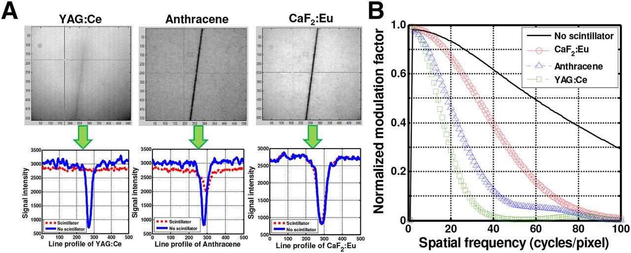
(A, upper) Resolution of the SBRI system was calculated by placing 3 scintillating membranes made from YAG:Ce, anthracene, and CaF2:Eu on top of thin tilted line, and images were acquired with ProEM CCD camera. (A, lower) On basis of 100-line profile algorithm, YAG:Ce lost most signal, compared with anthracene and CaF2:Eu (lost least signal). (B) Scintillator resolution was 6.7 μm for YAG:Ce, 2.5 μm for anthracene, and 1.2 μm for CaF2:Eu based on MTF calculation. Scintillator made from 50 mg of CaF2:Eu per mL with 100 μm thickness enabled the best resolution (1.2 μm).
To find the overall sensitivity of the SBRI system, we used a closed-disk 204Tl β source, which has a 37-kBq (1.0-μCi) radiation liquid in a 0.635-cm-diameter reservoir centered within a 2.54-cm disk (Spectrum Techniques). The source was placed in contact with the scintillating balloon and imaged with a 560-MHz gain at 60-s exposure (binning, 4 × 4). The experiment was conducted inside a light-tight black box with the room light off to avoid ambient light. The overall sensitivity of the system was calculated by selecting the region of interest (ROI) at the brightest spot in the center, expressed in terms of radioluminescence signal intensity.
Physical Properties of CaF2:Eu Phosphor
CaF2:Eu phosphor is a transparent material that prevents the scintillating balloon from being opaque even with high phosphor concentration. The low atomic number makes the scintillating balloon ideal for the detection of β particles due to small amount of back scattering (23). The phosphor-nonhygroscopic and relatively inert nature and sufficiently high resistivity to thermal and mechanical shock make CaF2:Eu phosphor suitable for in vivo use. Because CaF2:Eu transmits visible light well, the release of optical radiation from the decay of 18F-FDG can easily be transmitted to the wide-angle lens of the SBRI system. The low density of the CaF2:Eu phosphor (3.18 g/cm3) leads to high light output, with a decay constant of 0.84 μs for a scintillation emission peak at 435 nm. With its low Z value, CaF2:Eu phosphor is well suited for the detection of electrons (β particles) with a high light efficiency (19 photons/keV).
Fabrication
The initial step of the scintillating balloon fabrication started with making a poly-methylsiloxane (PDMS) mold (5-mm diameter and 8-mm depth). The PDMS with curing agent (1:10 mixture ratio) was poured on the master mold and cured at 70°C for 30 min. The cured PDMS was then peeled off from the mold to create the template for the scintillating balloon. The RTV solution (silicone to catalyst ratio, 10:1) with 50 mg of CaF2:Eu per mL mixed with 1 mL of dichloromethane anhydrous 99.9% acroseal was poured onto the PDMS template and cured under sterile conditions for 24 h. The balloon was peeled carefully from the PDMS template using a spatula. The scintillating balloon was then attached to the SBRI system using ultraviolet-curing Norland Optic Adhesive (Thorlabs, Inc.) under an ultraviolet lamp for 10 min. After the scintillating balloon was attached to the SBRI system, for 1 set of experiments we also attached a 500-μm-thick lutetium oxyorthosilicate (LSO) (75% or 28,000 photons/MeV) scintillating crystal in the front of the balloon using optical grease. We used LSO for its high relative light output/efficiency, low-energy resolution that influences scattering rejection (15%–20%), and faster scintillating decay time (LSO, 40 ns) (24). We hypothesized that the crystal tip in front of a scintillating balloon may give improved signal-to-noise ratio.
Experimental Procedure: Ex Vivo Imaging of Murine Plaque Uptake of 18F-FDG
Murine experiments were conducted according to a protocol approved by the Administrative Panel on Laboratory Animal Care. Macrophage-rich atherosclerotic lesions were created in the left carotid arteries of diabetic, hyperlipidemic FVB/NJ mice (n = 5), as studied extensively by our laboratory (25–28). In brief, 8-wk-old male mice (n = 5) were fed a high-fat diet containing 40% kcal of fat, 1.25% (by weight) cholesterol, and 0.5% (by weight) sodium cholate (D12109; Research Diets, Inc.). After 1 mo on the diet, diabetes was induced by 5 daily intraperitoneal injections of streptozotocin (40 mg/kg; Sigma-Aldrich). Two weeks after the initiation of diabetes, the left common carotid artery was ligated below the bifurcation with a 5-0 silk ligature (Ethicon) while the mice were anesthetized with 2% isoflurane. The nonligated right carotid served as an internal negative control. Two weeks after carotid ligation, mice were injected intravenously with 18F-FDG after 6 h of fasting. All mice were imaged on the same day to avoid system variability, so the dose of 18F-FDG was adjusted (43.66–51.06 MBq [1.18–1.38 mCi]) for each mouse to account for decay over sequential intravenous injections of 18F-FDG (i.e., the mouse imaged last received the largest 18F-FDG dose so the radioluminescence signal would be comparable with the first animal). A time line of the atherosclerotic plaque development in FVB mice and imaging with the SBRI system is depicted in Figure 5. One hour after injection, ligated left and nonligated (negative control) right carotid arteries were harvested and imaged intact with the CRi Maestro fluorescence imaging system (Fig. 6A, left). Then, the carotid arteries were cut open longitudinally and the lumen side imaged with a Histology Scope light microscope (Leica DM2000; Leica Microsystems Ltd.) at 40× magnification with 0.75 numeric aperture (Fig. 6A, right). These samples were placed near (500 μm) the HI PLAN SL objective (Leica). After this confirmatory imaging, the carotids were placed individually (lumen side facing up) on thick black paper, along with the heart (sectioned) as a positive control (because the myocardium takes up glucose) for ex vivo imaging with the SBRI system. The scintillating balloon was placed in contact with the tissue samples to capture all light converted from the β particles of the emission signal of 18F-FDG decay. After imaging the sample with the scintillating balloon alone, we attached the crystal tip and acquired a second set of images of the same sample. The exposure time was chosen to be 10 s based on prior experiments to achieve adequate signal intensity. Radioluminescence signal from the samples was calculated on the basis of the selected ROIs, all of the same size. The mean signal intensity was then calculated on the basis of the scintillating balloon-enabled fiber-optic radionuclide images.

Schematic diagram of animal study represents time line for atherosclerotic plaque development in FVB mice and imaging with SBRI system. IV = intravenous; STZ = streptozotocin.

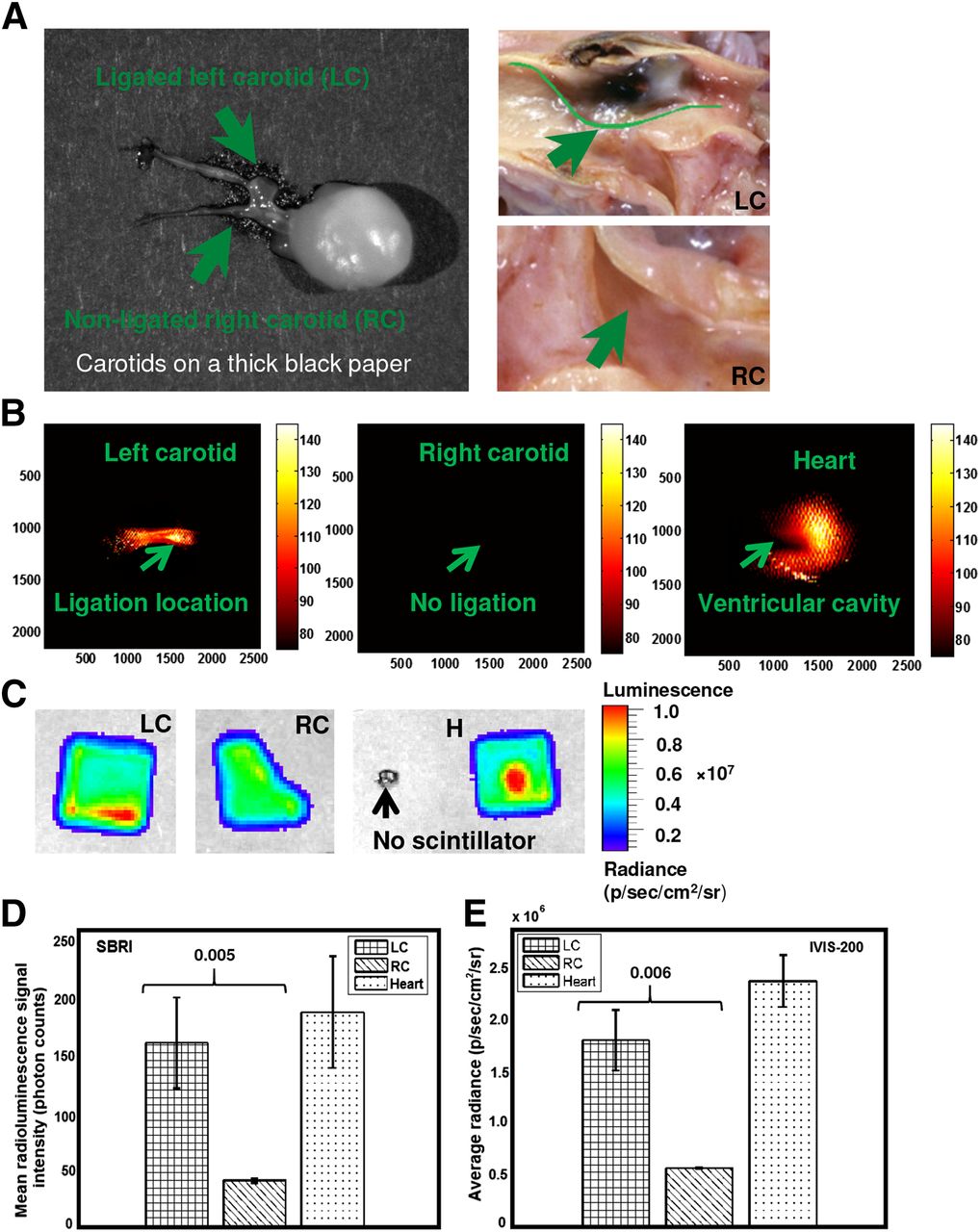
(A) A CRi Maestro photograph of both ligated left and nonligated right carotid arteries attached to heart captured immediately after extraction from mouse (left). A photograph taken with a Histology Scope (40×, light microscope, Leica DM2000) of lumen side of left carotid (upper right) and right carotid (lower right) arteries after longitudinal opening. Radionuclide imaging of ex vivo murine atherosclerotic plaque (1 h after intravenous injection of 18F-FDG) with SBRI (B) and confirmatory IVIS-200 imaging system (C). Ligated left carotid artery, nonligated right carotid artery (negative control), and heart are placed under LSO scintillating screen for IVIS-200 imaging. No radioluminescence signal was identified without scintillating screen. Mean radioluminescence signal from (D) scintillating balloon-enabled fiber-optic radionuclide images and (E) IVIS-200 images. About 4-times-higher statistically significant radioluminescence signal was detected from ligated left carotid arteries than nonligated right carotid artery (negative control) using SBRI system and confirmed by IVIS-200. H = heart (positive control); LC = ligated left carotid artery; RC = nonligated right carotid artery (negative control).
External Optical Imaging System (IVIS-200)
The experimental procedure with the IVIS-200 is described in our previous work (21). In brief, the IVIS-200 system provides for bioluminescence and fluorescence optical-based imaging and was used to validate the SBRI system. Samples were placed inside the light-tight imaging chamber and the field of view set to 1.5 cm for 18F-FDG samples, with the highly sensitive CCD camera system cooled to −90°C. For 18F-FDG imaging, the binning factor was set at medium (8 × 8 pixels), and an LSO scintillator screen was placed on top of the tissue sample. The bioluminescence mode was used to image the radioluminescence from the β particles of the positron emission signal from 18F-FDG radioactive decay, with the exposure time of 10 s. An average radiance was calculated with a unit of p/s/cm2/sr based on the IVIS-200 images after corrected for field flatness.
Autoradiography
The autoradiography procedure is described in our previous work (21). In brief, autoradiography was used to directly image the radiation emitted from the 18F-FDG tissue samples with high spatial resolution (29,30) for further validation. Carotid samples were placed in contact with a super resolution storage-phosphor screen (12.5 × 25.2 cm; PerkinElmer Inc.). Over a sufficient exposure time (48 h), emitted β particles were recorded as an image on the storage-phosphor screen. The film was then read out by a Cyclone interpreter using a spatial resolution of 600 dpi (PerkinElmer Inc.). The spatial distribution of radioisotope uptake of the tissue sample was recorded as digital light units per mm−2 using these techniques.
Statistical Analyses
A pairwise 2-sample Student t test was performed to compare ex vivo signal intensity from the 18F-FDG–enriched ligated left carotid and nonligated (control) right carotid arteries. The underlying distribution was found to be normally distributed according to QQ plots. Because all animals had similar weight and dose, these factors were not considered in the statistical analysis. Ex vivo analyses were performed using MATLAB software. We presented all values as mean ± SD. We considered a P value of less than 0.05 as statistically significant for all ex vivo analyses.
RESULTS
On the basis of the optimal phosphor analysis on the extracted signal described in the “Optimal Phosphor” section, we determined that the 100-μm-thick scintillator made from CaF2:Eu (254 photon counts) provided the highest radioluminescence signal, which was 68% and 20% brighter than YAG:Ce (81.4 photon counts) and anthracene (204 photon counts), respectively (Fig. 2C). The detection limit and overall radioluminescence signal sensitivity of the SBRI system was identified to be 1,320 (photon counts) based on a 37-kBq (1-μCi) closed-disk β source (Fig. 3B, upper and lower). Analyses based on MTF of an average of 100-line profiles (Fig. 4B) of each different phosphor on a tilted thin-line optical phantom showed that scintillator made from 50 mg of CaF2:Eu per mL with 100 μm thickness enabled the best resolution (1.2 μm), compared with YAG:Ce (6.7 μm) and anthracene (2.5 μm).
The SBRI system (Fig. 6B) detected a 4-fold-higher radioluminescence signal (Fig. 6D) from ex vivo macrophage-rich atherosclerotic carotid plaques after intravenous 18F-FDG, compared with the control right carotid arteries (1.63 × 10² ± 4.01 × 101 vs. 4.21 × 101 ± 2.09 × 100 photon counts, P = 0.006). We did not observe any significant benefit to adding the scintillator crystal tip (1.65 × 10² ± 4.07 × 101 vs. 4.44 × 101 ± 2.17 × 100 photon counts, P = 0.005). Also, high 18F-FDG signal was detected in the heart, as a positive control. Radionuclide imaging with the IVIS-200 system (Fig. 6C) confirmed the high radioluminescence signal (Fig. 6E) from the ligated left carotid arteries and heart (1.80 × 10⁶ ± 2.91 × 10⁵ vs. 5.69 × 10⁵ ± 6.51 × 10³ p/s/cm2/sr, left vs. right carotid, P = 0.006). As further confirmation, the scintillating balloon-enabled fiber-optic radionuclide images corresponded with findings from the Histology Scope (Fig. 6A) and autoradiography (Fig. 7).
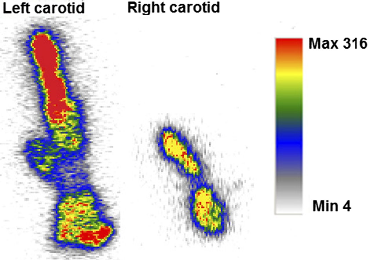
Autoradiography imaging for confirmatory purpose. Ex vivo autoradiography from mouse injected with 18F-FDG. Ligated left carotid artery showed high amount of 18F-FDG uptake, compared with nonligated right carotid artery. Max = maximum; Min = minimum.
DISCUSSION
We have demonstrated that our novel SBRI system was sensitive enough to detect carotid plaque uptake, ex vivo, of 18F-FDG at high resolution. On the basis of our analysis showing the higher sensitivity and resolution of CaF2:Eu than other phosphors, we chose the integration of a scintillating balloon made from CaF2:Eu. Thus, our integrated SBRI system shows promise as an intravascular radionuclide imaging approach to characterize coronary atherosclerosis.
We also found that use of an additional scintillator crystal tip was not necessary, because there was minimal change in detected signal level. However, the LSO scintillating crystal screen without the balloon (21) provided 2 orders of magnitude higher radioluminescence signal (2.6 × 10⁴ ± 1.4 × 10³ vs. 1.63 × 10² ± 4.01 × 101 photon counts) than ligated left carotid arteries. This higher signal is due to high relative light output or efficiency (75% or 28,000 photons/MeV) and low scatter rejection (15%–20%). We have identified that scintillating membrane made from 5 mg of YAG:Ce per mL showed less radioluminescence signal than the control. This unusual phenomenon could be explained with nonhomogeneous temperature-dependent dark current, hot pixel blemishes, and vibration from the camera during the time of image acquisition. Although the camera used deep thermoelectric cooling at −40°C to minimize these background signals in addition to using a filter during image processing. Thus, once the ROI was selected and averaged over a particular area, the radioluminescence signal intensities appeared to be less than the control due to this random effect.
Integrating the scintillating balloon into the fiber-optic system is a significant improvement over the separate scintillator screen we used in our prior feasibility study. A limitation of the current study is that we have not miniaturized the system sufficiently to perform in vivo experiments. The bottleneck is the 4.9-mm-diameter wide-angle lens, necessitating new designs and analyses with smaller lenses. We also aim to implement an SBRI system that combines the scintillating balloon and mechanical scanning in 1 small unit at the distal end of the catheter.
As any scintillator with a thickness as small as 1.0 mm provides an intrinsic efficiency close to 10% due to annihilation photons, we chose to use a scintillating balloon with a thickness of 0.1 mm and a scintillating crystal with a thickness of 0.5 mm. Because of this extremely thin scintillator (0.1 or 0.6 mm), the SBRI system eliminates a significant amount of annihilation photons, which would have come from distant tissues and hinder the imaging of the local 18F-FDG uptake in the plaque. We used a higher 18F-FDG dose in this feasibility study than typically used in mice (7.4 MBq [0.2 mCi]) (31), though similar to our prior feasibility study of murine tumors (32). The typical recommended dose of 18F-FDG for an adult is 370–740 MBq (10–20 mCi), so ur study used approximately 2 times the usual human dose, when adjusted for weight (33). Although we were encouraged that a 4-fold-higher 18F-FDG signal was detected from the plaques, future in vivo experiments will need to assess lower 18F-FDG doses.
The utility of a radiation-sensitive catheter to detect and localize the lesions will depend on both the physical properties of the radionuclide and the biologic behavior of the selected tracer. Although external imaging uses γ and x radiation, this is not desirable for intravascular detection (34). Because γ and x radiation is penetrating, activity outside the vessel (e.g., in the myocardium, kidneys) could create a potentially overwhelming background, making it difficult, if not impossible, to see the relatively weak signal from the vulnerable plaque. Therefore, β radiation from 18F-FDG was used (few-millimeter path length) for the radionuclide imaging with the SBRI system.
Our novel system was designed to capture only β particles as we have used a thin 100-μm-thick scintillating balloon. Although a 300-keV charged β particle is likely to deposit all of its energy in the 100 (balloon only)- or 600 (balloon with crystal tip)-μm-thick scintillator, γ particles will deposit a small fraction of its energy because of Compton interaction. Therefore, it is unlikely that the γ particles will interact with the scintillator to create background noise. Thus, subtraction of the γ radiation signal was not considered. In addition, we performed experiments to confirm that no γ particles interacted with the radioluminescence signal from the sample. Before imaging the carotids with the SBRI system, we placed a slice of 18F-FDG–enriched heart in close proximity of the carotids (0.5 cm) and observed no background signal (Fig. 6B). Even with the scintillating balloon so close to the γ particles from the heart, we were still able to image the plaque location in the ligated left carotids without any background noise. The experimental results mentioned here can be explained by the geometric sensitivity of the SBRI system. As atheroma typically surrounds the vessel lumen, particles that are discharged into the vessel lumen are likely to be detected, whereas those emitted toward the basement membrane of the vessel (traveling away from the scintillator) will not be detected.
Despite significant advancements in medical and device-based therapies, cardiovascular diseases remain the number one cause of death in the United States (35). The early detection of atherosclerosis and prevention of myocardial infarction and sudden cardiac death still remain important goals. Although, molecular imaging has become part of the toolbox in basic science and numerous molecular imaging strategies exist for atherosclerosis detection, there remains a substantial translational gap for molecular imaging of coronary atherosclerosis in patients. The results with our SBRI system for 18F-FDG detection indicate several promising features for the future application to intravascular imaging of vulnerable coronary plaque.
CONCLUSION
Our fiber-optic radionuclide imaging system with an integrated scintillating balloon provides high resolution and sensitive detection of 18F-FDG uptake by murine atherosclerotic plaques. This is a promising approach for intravascular molecular imaging of atherosclerosis.
DISCLOSURE
The costs of publication of this article were defrayed in part by the payment of page charges. Therefore, and solely to indicate this fact, this article is hereby marked “advertisement” in accordance with 18 USC section 1734. This study was supported by the NIH T32 Multi-Disciplinary Training Program in Cardiovascular Imaging at Stanford (T32EB009035) and a Western States Affiliated American Heart Association Postdoctoral Fellowship (13POST17290051). No other potential conflict of interest relevant to this article was reported.
Acknowledgments
We gratefully acknowledge the help of Dr. Guillem Pratx for the MTF algorithm, the Stanford small-animal imaging facility, the Stanford animal facility for accommodating our instrument, and PETNET for providing 18F-FDG.
Footnotes
Published online Apr. 9, 2015.
- © 2015 by the Society of Nuclear Medicine and Molecular Imaging, Inc.
REFERENCES
- Received for publication December 16, 2014.
- Accepted for publication March 18, 2015.


