


Article Figures & Data
Figures
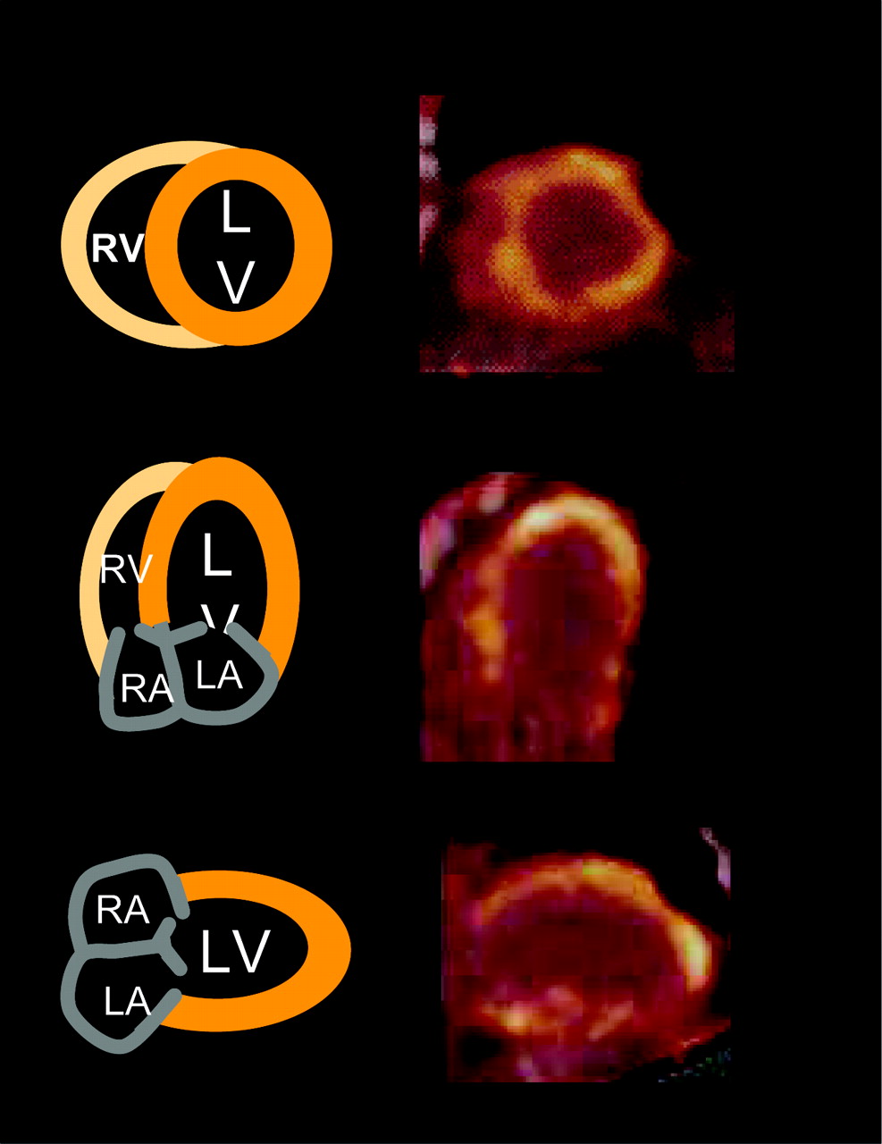
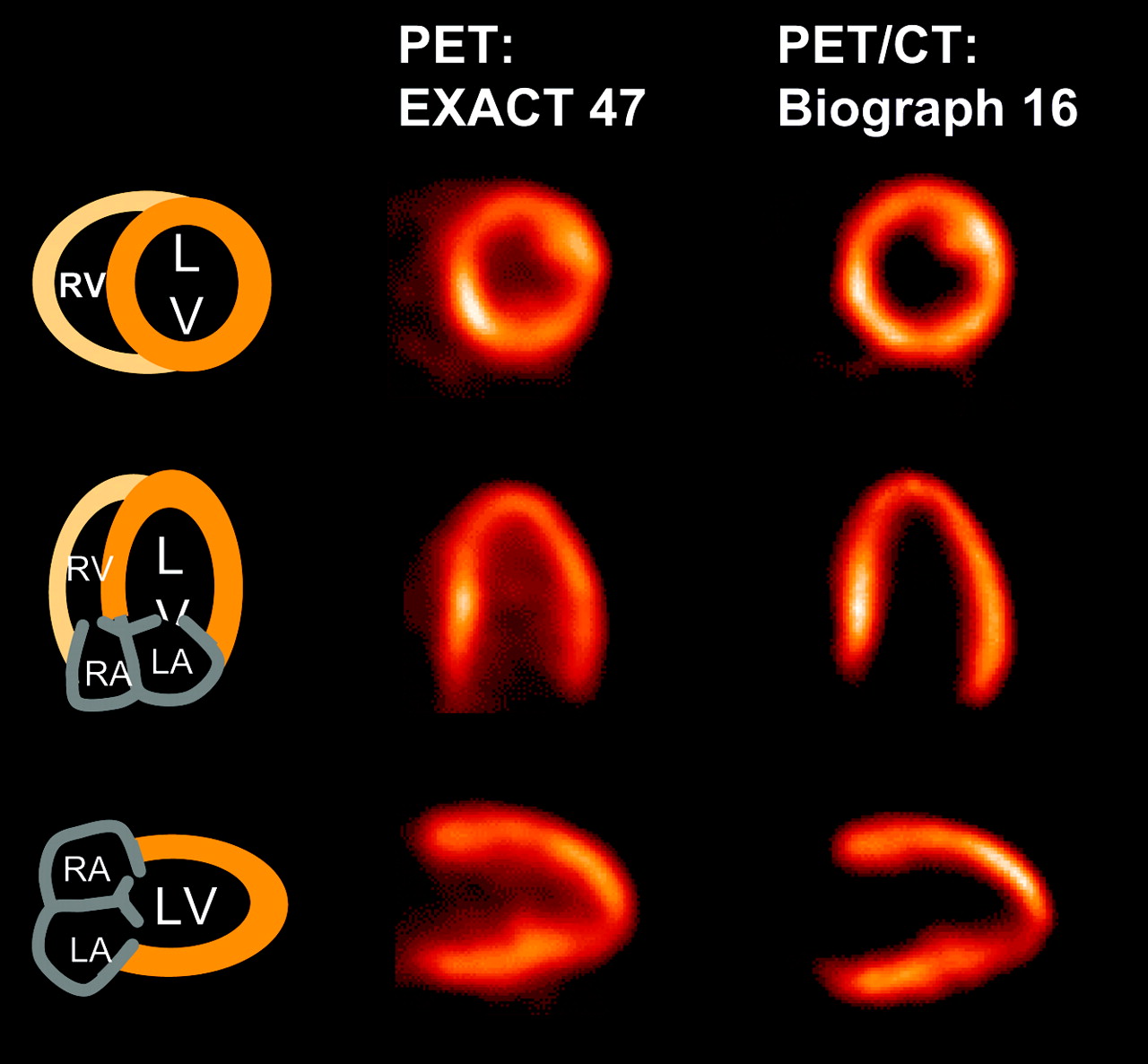
- FIGURE 1.
Sample 18F-FDG study from our institution in 3D mode with both BGO and LSO as detector material demonstrates the excellent image quality provided by state-of-the-art PET/CT scanners (Biograph 16; Siemens), compared with conventional scanners (EXACT 47; Siemens). LA = left atrium; LV = left ventricle; RA = right atrium; RV = right ventricle.
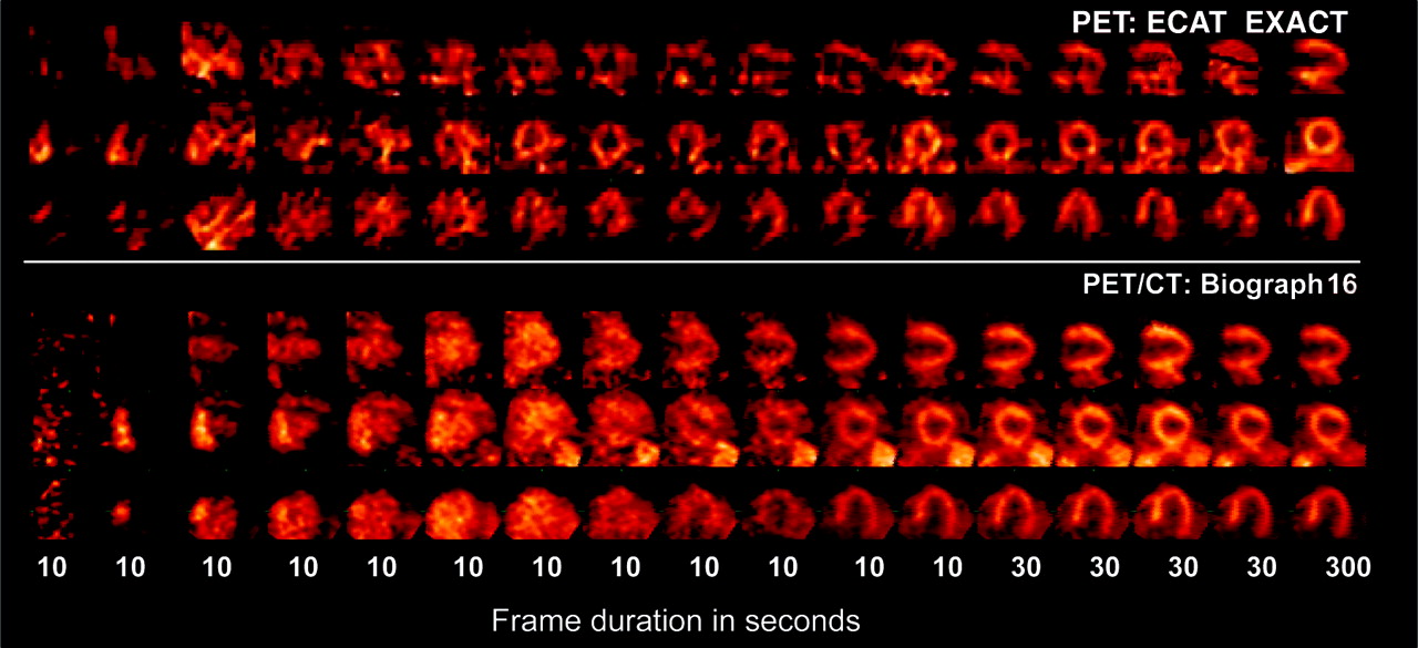
- FIGURE 2.
Increased sensitivity of LSO-based PET systems is demonstrated in these dynamic series after injection of 555 MBq of 13N ammonia. The 3 top rows show long- and short-axis images of tracer uptake using conventional PET scanner (ECAT EXACT; Siemens). The 3 bottom rows show similar protocol with LSO-based system (Biograph 16; Siemens). Note increased signal-to-noise ratio and improved delineation of cardiac structures during 10-s frames in PET/CT data.
- FIGURE 3.
Influence of respiratory gating on cardiac motion is demonstrated in this 13N-ammonia study. With acquisition time of 10 min after tracer injection, list-mode data from 2 to 10 min were charted by histogram into 6 respiratory and 2 cardiac cycles. Images show end-diastolic frames in end inspiration and end expiration. Approximated, most apical position in both respiratory states is marked with yellow line. Maximal spatial difference is 8 mm. LA = left atrium; LV = left ventricle; RA = right atrium; RV = right ventricle.
- FIGURE 4.
Example of PET images attenuation corrected by misaligned CT image with artifacts in anterolateral wall of left ventricle. Artifacts resulted from motion associated with deep breathing of patient during CT scan. Resulting AC map is misaligned with PET emission data. Incorrect AC results in artifactual defects most commonly in anterolateral wall. LA = left atrium; LV = left ventricle; RA = right atrium; RV = right ventricle.
- FIGURE 5.
Application of emission-driven AC. Initial data showed significant mismatch between PET and CT data used for AC in patient without regional perfusion defects. Apparent reduced tracer uptake in anterolateral segments is clearly visible in fused image display and in polar map (top). On basis of assumption that tracer uptake (even if reduced) can be emitted only from cardiac tissue, attenuation map was modified and image reconstruction repeated, resulting in substantial recovery of tracer uptake. Ant = anterior; Inf = inferior; Lat = lateral; Sep = septal.
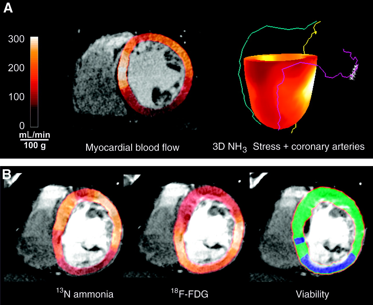
- FIGURE 6.
(A) Visualization of CT angiography (CTA) and PET data requires integrative display format. Myocardial blood flow under stress conditions with 13N ammonia was calculated using dynamic data. These regional flow values were mapped in color code onto segmented wall from coronary angiography study. In addition, coronary tree was manually extracted and superimposed on 3D polar map of myocardial blood flow. (B) 13N-ammonia and 18F-FDG retention from viability examination were mapped onto myocardial wall. The combination of these 2 tracer studies provides tissue classification, which can be used to describe myocardium specifically. Blue = mismatch or hibernating myocardium; green = normal; LV = left ventricle; RCA = right coronary artery; RV = right ventricle.


Tables
Characteristic BGO (Bi4Ge3O12) LSO (Lu2SiO5:Ce) GSO (GdSiO5:Ce) Density (g/cm3) 7.1 7.4 6.7 Effective Z 75 65 59 Attenuation length at 511 keV (mm) 10.4 11.4 14.1 Light yield (photons/MeV) 9,000 26,000 10,000 Decay time (ns) 300 40 60 Emission (nm) 480 420 440 Parameter Biograph 16 (Hi-Rez) Biograph 64 Gemini GXL Gemini GXL64 Discovery ST CT Slices 16 64 16 64 16 Rotation speed (s) 0.42 0.33 0.5 0.4 0.5 Temporal resolution (ms) ∼105 ∼90 ∼120 ∼100 ∼120 Spatial resolution (line pairs/cm) 30 30 24 24 15.4 PET Scintillator LSO LSO GSO GSO BGO Detector dimensions (mm) 4 × 4 × 25 4 × 4 × 25 4 × 6 × 30 4 × 6 × 30 6.3 × 6.3 × 30 Axial field of view (cm) 16.2 16.2 18 18 15.7 Sensitivity (cps/kBq) 4.5 4.5 8.3 8.3 9.3 (3D) Peak noise equivalent count rate (kcps) 93 93 70 70 63 (3D) Transverse resolution (mm) 4.5 4.5 5.2 5.2 6.2 (3D) Axial resolution (mm) 5.6 5.6 5.5 5.5 7.0 (3D) Data were obtained from the vendors of the PET/CT systems: Siemens (Biograph 16 and Biograph 64), Philips (Gemini GXL and Gemini GXL64), and GE Healthcare (Discovery ST).
Study Effective radiation dose (mSv) PET 18F-FDG (370 MBq) 7.0 13N-NH3 rest/stress (2 × 550 MBq) 2.2 82Rb rest/stress (2 × 740 MBq) 5.0 H215O rest/stress (2 × 740 MBq) 1.4 Transmission 68Ge rod sources 0.08–0.13 Multislice CT Calcium scoring 1.5–6.2 CT angiography 6.7–13.0 CT-based PET attenuation correction 0.23–5.66 Parameter PET Multislice CT Left ventricular function ++ +++ Coronary calcification − ++ Coronary angiography − ++ Perfusion +++ + Metabolism +++ − Viability +++ + (?) Plaque morphology − + Molecular imaging ++ −
In this issue


Jump to section
Related Articles
Cited By...
- Shine-Through in PET/MR Imaging: Effects of the Magnetic Field on Positron Range and Subsequent Image Artifacts
- Hybrid PET/MR Imaging of the Heart: Potential, Initial Experiences, and Future Prospects
- Myocardial Perfusion Imaging Versus CT Coronary Angiography: When to Use Which?
- Single-Phase CT Aligned to Gated PET for Respiratory Motion Correction in Cardiac PET/CT
- Decreased Perfusion in the Lateral Wall of the Left Ventricle in PET/CT Studies with 13N-Ammonia: Evaluation in Healthy Adults
- Incremental Prognostic Value of Gated Rb-82 Positron Emission Tomography Myocardial Perfusion Imaging Over Clinical Variables and Rest LVEF
- Initial Characterization of an 18F-Labeled Myocardial Perfusion Tracer
- F-18-Fluorodeoxyglucose Positron Emission Tomography Imaging-Assisted Management of Patients With Severe Left Ventricular Dysfunction and Suspected Coronary Disease: A Randomized, Controlled Trial (PARR-2)
- Characterization of Plaques Using 18F-FDG PET/CT in Patients with Carotid Atherosclerosis and Correlation with Matrix Metalloproteinase-1