


Abstract
There have been major advances in PET technology that cumulatively have helped improve image quality, increased the range of applications for PET, and contributed to the more widespread use of PET. Examples of these technologic advances include whole-body imaging, 3-dimensional imaging, new scintillator materials, iterative reconstruction algorithms, combined PET/CT, and preclinical PET. New advances on the immediate horizon include the reintroduction of time-of-flight PET, which takes advantage of the favorable timing properties of newer scintillators; the integration of PET and MRI scanners into a dual-modality imaging system; and the possibility of further significant improvements in spatial resolution in preclinical PET systems. Sensitivity remains a limiting factor in many PET studies. Although, conceptually, huge gains in sensitivity are still possible, realizing these gains is thwarted largely by economic rather than scientific concerns. Predicting the future is fraught with difficulty; nonetheless, it is apparent that ample opportunities remain for new development and innovation in PET technology that will be driven by the demands of molecular medicine, notably sensitive and specific molecular diagnostic tools and the ability to quantitatively monitor therapeutic entities that include small molecules, peptides, antibodies, nanoparticles, DNA/RNA, and cells.
On the surface, the design of PET scanners appears to have changed little over the past 15 years. However, beneath the sleek exteriors, there has been a revolution in the technologies and methods that are now used. Many talented scientists in academia and industry have contributed to the conception of these ideas and have then worked hard to reduce them to practice—in the process dramatically improving the spatial resolution, sensitivity, and counting rate performance of PET systems and, in doing so, expanding the range of applications in which PET can provide effective information, whether that be in the context of a clinical diagnostic study, in clinical or basic human research, or in preclinical research.
In the first part of this discussion, I will take a retrospective look at some of the key advances in PET technology over the past 20 years and the impact they have had on our field. This discussion will demonstrate the continued and sustained innovation that has been instrumental in making PET the powerful translational molecular modality that it has unquestionably become. In the second part, I will look to the near future and highlight 3 emerging themes in PET technology that in my opinion have the possibility of becoming the key advances of the next several years. Finally, I will take some wild guesses regarding the design and ultimate performance of the PET scanners of the far future. Naturally, this is a highly selective viewpoint that reflects the author's own biases and interests and with which some, and perhaps many, readers will disagree. So, the reader is forewarned! But if it generates scientific discussion and debate and stimulates enthusiasm for tackling the many technologic (and in some cases economic) barriers that prevent us from realizing the theoretically achievable performance of molecular imaging with PET, then it will have served its purpose. A final disclaimer is that this is not a review article; therefore, the references cited are highly selective and are not intended to serve as an encyclopedic record of the many contributions in the literature relevant to each of the topics covered.
THE PAST: A REVIEW OF MAJOR ADVANCES IN PET TECHNOLOGY SINCE 1990
Presented here, in rough chronologic order, are what I consider to be some of the most influential advances and changes in PET instrumentation and methods over the past 20 years (Fig. 1). In addition, there have of course been tremendous developments in computational power—and a migration from analog electronics to sophisticated digital electronics—that have been thoroughly exploited in modern PET scanners and have been enabling factors in many of the changes. Cumulatively, all these advances have had a positive impact on every application of PET.

Images and photographs illustrating the major advances in PET instrumentation and methods since 1990 discussed in text: whole-body PET (image courtesy of Dr. Magnus Dahlbom, UCLA) (A), 3D PET (B), LSO and related scintillators (photograph courtesy of Dr. Charles Melcher, Siemens) (C), iterative reconstruction methods (images courtesy of Dr. Richard Leahy, USC) (D), PET/CT (image courtesy of Dr. David Townsend, University of Tennessee) (E), and preclinical PET (mouse image courtesy of Dr. Craig Abbey, UCSB) (F).
Whole-Body PET
In the 1980s, many PET studies were focused on the brain or the heart, and the design of most PET scanners reflected these applications, with an axial field of view just barely large enough for these organs, and with data acquired at 1 bed position. Although the idea of moving the bed through the scanner and acquiring data at a set of contiguous or overlapping bed positions seems obvious in retrospect, this concept and its implementation (1,2) were to change PET forever. The ability to view the whole body opened up clinical applications involving disseminated disease and, in particular, the use of PET for whole-body surveys for finding both primary tumors and metastasis (3) and for monitoring response to chemotherapy. Whole-body imaging therefore directly led to the primary clinical application of PET today and to reimbursement. In the future, the role of whole-body PET can be expected to grow, because it will likely also be critical for monitoring some cellular, DNA- or RNA-based, and immunologic therapies, and roles also can be foreseen in imaging systemic disease, for example, infectious disease, vulnerable plaque, and inflammation.
3-Dimensional (3D) PET
Human PET has been limited largely by scanner sensitivity for many years, with improvements in the spatial resolution of the detectors outstripping gains in counting statistics. Thus, there has been a downward trend in the number of counts detected per detector pair or resolution element with time. Three-dimensional PET, which involved removal of the slice-collimating septa used in many PET systems in the 1980s and early 1990s (4,5), allowed coincidences to be formed between any detector ring in the PET scanner, producing an approximately 5- to 7-fold increase in sensitivity without any increase in the number of detectors in the system. A number of dedicated 3D scanners also were developed around this time (e.g., (6,7)). Three-dimensional PET found an immediate application in the brain but has seen slower acceptance in the rest of the body, because 3D acquisition results in much higher counting rates, higher scatter fractions, and higher numbers of random coincidences, such that with relatively dim and slow scintillators such as bismuth germanate (BGO), significant benefits were not necessarily readily obtained. But with the advent of bright, fast scintillators, in which better energy and timing resolution can be obtained, and in which pulses can be integrated for a shorter time, these effects can be mitigated and more of the sensitivity benefit of 3D PET can be realized. Many people contributed to the development of 3D PET, through early design of 3D-only scanners and modification of traditional 2-dimensional BGO scanners to enable 3D data acquisition, as already discussed (4–7), and through development of reconstruction algorithms that could properly use the 3D data (e.g., (8–11)). Nonetheless, the clinical systems of today, even in 3D mode, still rarely realize their full resolution potential (typically 4–6 mm), because sensitivity is still a limiting factor that results in reconstruction of most clinical studies somewhere in the 8- to 12-mm range to provide signal-to-noise ratios (SNRs) acceptable for diagnostic interpretation.
New Scintillator Materials
In the early 1990s, there was a dilemma in choosing a detector material for use in a PET scanner. The 2 main choices for scintillator material were NaI(Tl), traditionally used in γ-cameras, and BGO (Table 1). But neither has ideal properties. As mentioned, the slow decay time and low light output of BGO leads to relatively poor timing and energy resolution, yet the high stopping power provides good detector efficiency at 511 keV. The performance of BGO PET scanners in 3D mode was clearly limited by dead time, randoms, and scatter. NaI(Tl) provides better energy resolution (allowing the use of a higher energy threshold to reduce the scatter content of 3D datasets) and was used successfully in several 3D-only PET systems (e.g., (6)); however, timing resolution is still relatively poor, dead time is high, and the stopping power is considerably worse than for BGO. Therefore, a major breakthrough has been the development of new scintillator materials, particularly lutetium oxyorthosilicate (LSO) (12) and related materials such as LYSO (LSO doped with a small amount of yttrium) (13), mixed lutetium silicates, and lutetium fine silicates (14). These scintillators are dense, bright, and fast, yielding excellent timing resolution and reasonable energy resolution (not as good as one might predict for their brightness, because of nonlinearities in the production of scintillation light), and they have a stopping power only slightly inferior to that of BGO. These properties, when coupled with fast, high-throughput electronics, significantly improve the performance of 3D PET scanners made using these materials. Because they are brighter than BGO, these scintillators also permit more crystal elements to be decoded per photomultiplier tube, thus helping control costs as the trend toward more detector elements in a PET scanner has continued.
Properties of PET Scintillators
Iterative Reconstruction Methods
Filtered backprojection methods, including 3D reconstruction algorithms based on filtered backprojection (8–11), have the attractive properties of being linear, and computationally fast, but can easily lead to significant artifacts caused by a combination of low statistics (both in the original emission data and with additional possible contributions from normalization, attenuation correction, and randoms correction) and sampling considerations. These methods also simplistically model the geometry of the scanner with perfect pointlike detectors and give the same weight to projection elements containing large numbers of counts as to those containing just a few counts. For these reasons, much effort has been devoted to developing iterative reconstruction algorithms that weight the data according to their statistical quality and that accurately model the geometry of the imaging system, including effects such as intercrystal scatter and depth of interaction effects and nonuniform sensitivity along a line of response. These methods can also handle the incorporation of corrections for attenuation and normalization in a statistically optimized fashion. The net result is that, in general, iterative algorithms result in reconstructed images that have a more favorable tradeoff between SNR and spatial resolution and in which streak artifacts, common with filtered backprojection methods (e.g., around the bladder in 18F-FDG studies), are effectively eliminated (15–17). Thus, these methods have now been widely adopted. The largest drawback has been the computational cost of these algorithms, which, because of the rapidly increasing number of detectors in PET scanners, has increased even faster than can be kept up with by advances in the speed of computers. Fortunately, accelerated versions of these algorithms are available that render them practical for routine use (18).
PET/CT
The introduction of combined PET and CT scanners in a tandem configuration in the latter part of the 1990s (19,20) led to a paradigm shift in the practice of clinical PET. By providing registered PET and CT data, this configuration enabled regions of increased 18F-FDG accumulation on the PET image to be directly correlated with their anatomic locations on the CT scan, improving the sensitivity and specificity of PET for lesion detection. The dramatic impact of this technology is best appreciated by observing that within 5 years of the introduction of the first PET/CT scanners, they were accounting for greater than 90% of all PET scanner sales. The combination of PET and CT has important secondary benefits as well. The CT scan, with appropriate consideration for differences between the spectrum of x-ray energies produced in CT and the monoenergetic 511-keV photons detected in PET, can be used to correct for photon attenuation in PET (21), eliminating the need for PET transmission sources and scans. The CT scan also has the potential to be used to estimate the scattered events in the PET scan and to correct for partial volume errors. Although the adoption of this technology has been rapid and widespread, several important technical challenges remain, including the differing effects of physiologic motion in PET and CT because of the different acquisition protocols (22) and the effect of CT contrast agents when using the CT for PET attenuation correction (23,24).
Preclinical PET
Although PET has been used for research studies in animals for a long time, most applications were in large-animal models such as the pig and dog for cardiovascular research and the nonhuman primate for neuroscience research. Most of these studies were performed on human PET scanners, and little work was done in rodent models because the resolution of clinical scanners was insufficient for all but the crudest of studies. The combination of large PET scanners and expensive animal models also restricted these types of studies to the largest research centers. But the development of high-resolution, dedicated animal PET scanners during the 1990s (25–28) brought PET technology to a whole new set of investigators in the biologic sciences and, as a preclinical tool, to the pharmaceutical and biotechnology industry. Just as with human PET scanners, this technology has progressed from academic laboratories to small companies and now to the major medical imaging corporations. Although small-animal scanners are based on the same technologies as are used in clinical systems, the requirements (high resolution, high sensitivity, small field of view) and the imaging environment (low attenuation, low scatter, low counting rates) are quite different, leading to very different tradeoffs in the design. Preclinical PET has now become firmly established as a discipline in its own right and has helped position PET as a leading translational tool in the field of molecular imaging, allowing PET tracers and quantitative assays to be used seamlessly across species, from mouse to patient.
THE PRESENT AND THE NEAR FUTURE
Over the years, there have been several moments at which one might have felt that PET technology had reached its full potential and that perhaps the major innovations were behind us, but as the 6 examples just given illustrate, there have continued to be breakthroughs over the past 20 years that have fundamentally changed the practice and application of PET. We find ourselves asking the same question today—that is, Has PET technology now matured to a level at which we can expect only incremental changes, or will there be yet another wave of major breakthroughs? Predicting the future is fraught with danger, but nonetheless, some developments already well under way are likely to significantly affect PET over the next few years, and I have selected 3 promising areas to explore in more detail. But first, for the reader to appreciate some of the points that will be made, a quick review of basic PET physics is in order.
Figure 2 shows an 18F-FDG molecule inside the body. When the radioactive 18F atom on the molecule decays, a positron is emitted and interacts with surrounding electrons and atoms in the tissue, scattering off them and quickly losing energy. Within a short distance and time, the positron will have slowed to thermal energies and will undergo annihilation, with a nearby electron (in the process the 2 particles disappear) producing 2 back-to-back annihilation photons, each of which carries away an energy of 511 keV. Annihilation is a wonderful example of Einstein's famous E = mc2 equation, where the summed masses (m) of the positron and electron are converted into energy (E), with a constant of proportionality equal to the speed of light (c) squared. What we actually image in PET is the distribution of annihilation sites in the body, but because the distance from the decaying molecule to the annihilation site (known as the positron range) is fairly short, this distribution is a good approximation of the distribution of the radiolabeled molecules that we actually seek to image.
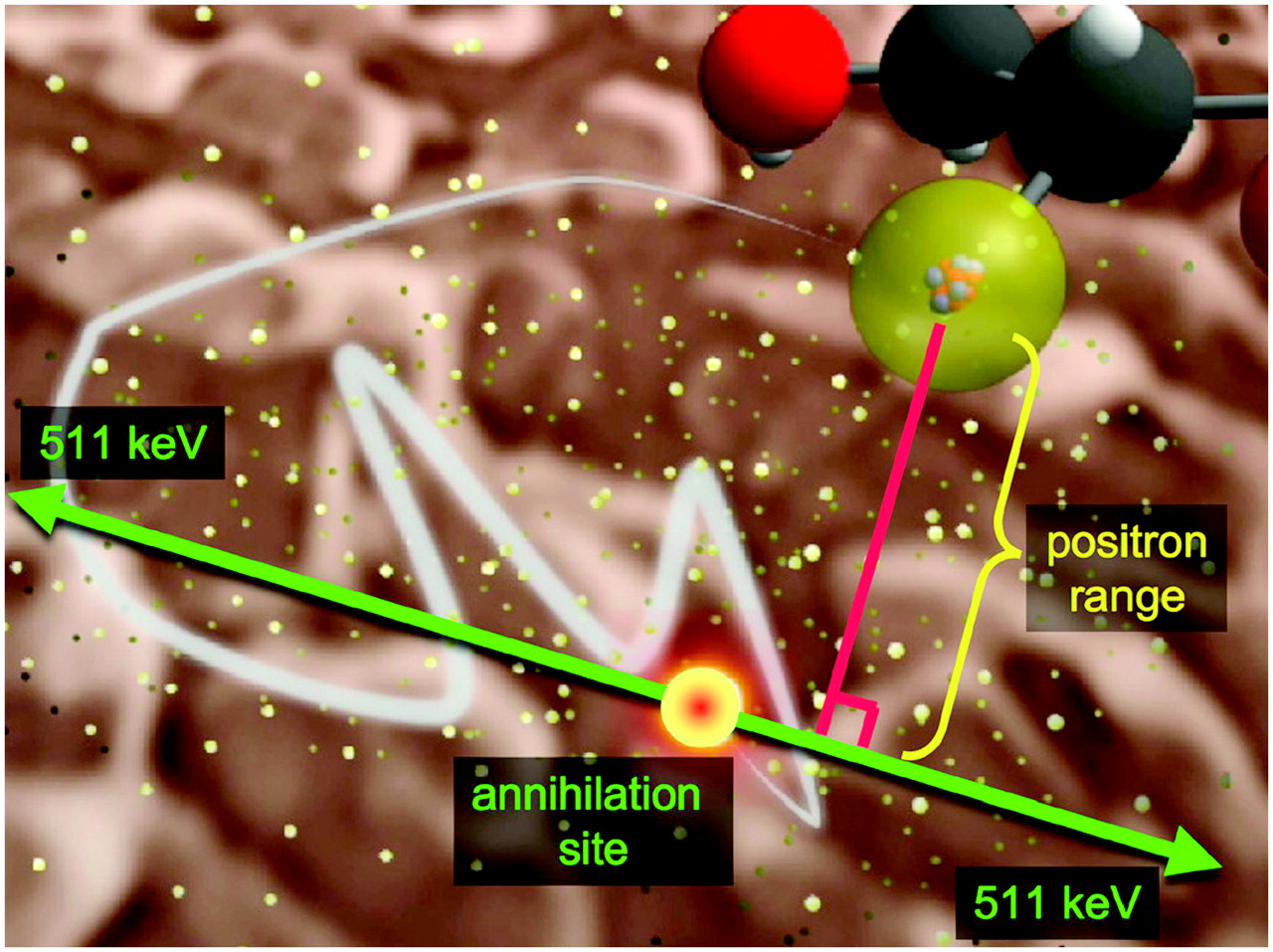
Basic physics of PET. 18F atom (yellow) on FDG or FDG-6-phosphate molecule decays, emitting positron that scatters in tissue until it loses enough energy to undergo annihilation with an electron, in which mass of positron and electron are converted into 2 back-to-back 511-keV photons.
Time-of-Flight (TOF) PET
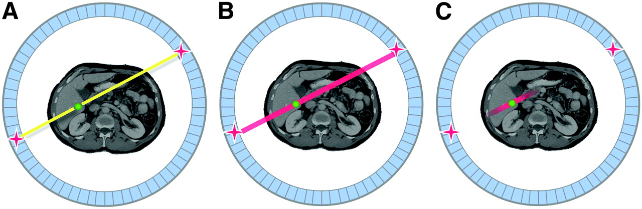
In conventional PET, a valid event is formed when the 2 coincident 511-keV annihilation photons are detected within some prespecified timing window, typically on the order of 8–14 ns for detectors based on scintillators such as BGO and NaI(Tl). The 2 detectors in which interactions are measured determine a line along which the original annihilation site must lie (Fig. 3A). The location of the annihilation site along that line is unknown and must be recovered by image reconstruction. The image reconstruction algorithm, with no other information at its disposal, assumes that all possible locations of the annihilation site along the line are equally likely (Fig. 3B).

Illustration of TOF PET: detection of 2 annihilation photons in PET scanner (A), uniform-probability weighting of annihilation site in standard PET (B), and use of TOF information to constrain location of annihilation site during image reconstruction (C).
In TOF PET, the actual time difference in the arrival of the 2 annihilation photons at the detectors is recorded (29). The time difference increases the farther the annihilation site is from the point midway between the 2 detectors. Modern clinical PET scanners typically are capable of an isotropic spatial resolution in the 4- to 6-mm range. Therefore, if we wanted to use the TOF effect to pinpoint the annihilation site to about 5 mm and completely eliminate the need for image reconstruction, then the photon arrival times (given that the speed of light is 3 × 10⁸ m/s) would need to be recorded with a precision of approximately 30 ps! Detectors and electronics capable of such a timing resolution are not available; however, a timing resolution of a few hundred picoseconds is feasible. This can be used to constrain the reconstruction algorithm, because it localizes the annihilation site to within a few centimeters, and thus the reconstruction of that event can be weighted accordingly (Fig. 3C). The approximate improvement in SNR over that obtained with non-TOF PET is given by Eq. 1where D is the diameter of the object being imaged, c is the speed of light, and Δt is the timing resolution of the system.
Many will recall that TOF PET was all the rage in the mid-1980s but, after careful investigation, was soundly rejected as an approach in clinical PET systems. So why, some 20 years later, is TOF PET making a comeback, and why is it likely here to stay this time? The difference is due to the scintillators now available, together with improved fast timing electronics. In 1990, the only scintillators fast enough to provide any reasonable level of TOF information for PET were BaF2 and CsF (Table 1). With both these scintillators, a timing resolution of around 550–750 ps was achieved in PET systems. Unfortunately, the modest SNR gain at this timing resolution, predicted by Equation 1, was more than offset by the much lower efficiency of these scintillators compared with that of BGO (reducing the number of counts detected for a given dose and reducing SNR). There were also many issues with the stability of these early systems (29).
Recently, it has become clear that excellent timing resolution can be achieved with some of the newer scintillators such as LSO and LYSO, and because these materials have good stopping power, there is no compromise in detector efficiency. With a single pair of detectors, a timing resolution of 220 ps has been measured with LSO (Bill Moses, written communication, 2006), and in a recent commercial LYSO TOF PET system (Philips), a 600-ps timing resolution has already been achieved. A TOF PET system based on LaBr3 also is being developed (30) and promises an even better timing resolution coupled with outstanding energy resolution, albeit with some compromise in sensitivity because of the lower stopping power of LaBr3 relative to that of LSO and LYSO.
It now appears possible to actually realize the gains predicted by Equation 1, and in a patient, these gains are significant indeed. For example, if one takes a fairly favorable scenario of a 40-cm-diameter patient, imaged on a TOF PET scanner with 300-ps timing resolution, one would expect an SNR gain of a factor of 3. In a less favorable scenario, of a 30-cm-diameter patient, with 600-ps timing resolution, then the SNR gain is still predicted to be a factor of 1.8. These gains are larger than the true gain realized with the introduction of 3D PET and will make a significant difference to the practice of PET (31,32), permitting some combination of faster imaging, lower injected dose, improved SNR, or improved spatial resolution. It is also worth noting that the improvements from TOF PET actually are greater in larger patients (larger D in Eq. 1). Given that image quality is a major problem in heavier patients (more attenuation and scatter), that obesity is on the rise, and that obesity leads to health-related problems that may require diagnostic PET scans, TOF PET may be an even more important advance than we currently realize.
Very-High-Resolution Preclinical PET
The requirement of imaging small structures in animal PET has helped to push the spatial-resolution frontiers for PET. Before the introduction of dedicated preclinical PET scanners, it was commonly accepted that the resolution of PET was limited to approximately 2 mm (it turns out, for human whole-body imaging, that this is correct). But preclinical PET scanners that can reconstruct images with a spatial resolution of 1 mm or less already exist (e.g., (28,33–35)); therefore, this limit clearly does not apply to animal studies. So, the question is, What is the difference between animal imaging and patient imaging that permits higher spatial resolution, and how much further can the spatial resolution be improved in preclinical applications?
Spatial resolution in PET is determined by several factors. The first factor, positron range, is the distance the positron travels from its point of emission to its point of annihilation, as defined in Figure 2. Because the annihilation sites, and not the site of the radioactive atoms, are imaged by PET, some blurring is introduced into the image. The amount of blurring depends on the energy with which the positrons are emitted and is radionuclide-dependent. A second factor, non-colinearity, is a result of nonzero momentum of the positron and electron at the time of annihilation, resulting in a slight angular deviation of the 2 annihilation photons about the assumed 180°. This factor is illustrated, in exaggerated form, in Figure 4; the amount of blurring due to non-colinearity is given roughly by 0.022 × detector separation. A third factor is detector geometry. A detector of width d results in a triangular coincidence response function with a full width at half maximum of d/2. Thus, achieving a 2-mm resolution would require that the detector elements be smaller than 4 mm. The thickness of the detector (typically 1–3 cm) also has some influence on spatial resolution through parallax errors. In a typical ring-geometry scanner, this influence leads to degradation of spatial resolution as one moves away from the central axis of the scanner. A fourth factor is detector interaction physics. Unfortunately, even when one uses the scintillator with the highest stopping power available (BGO), the most likely interaction in the detector at 511 keV is Compton scatter, where the photon will interact, deposit just some of its energy, change direction, and then, particularly in thick detectors, have a significant probability of interacting in adjacent detectors. Thus, the energy is deposited at 2 or more locations in the scanner, and there is no simple method to determine the first point of interaction that corresponds to the desired positional information. The result is some additional data blurring that depends on the scintillator material and the thickness of the detectors.
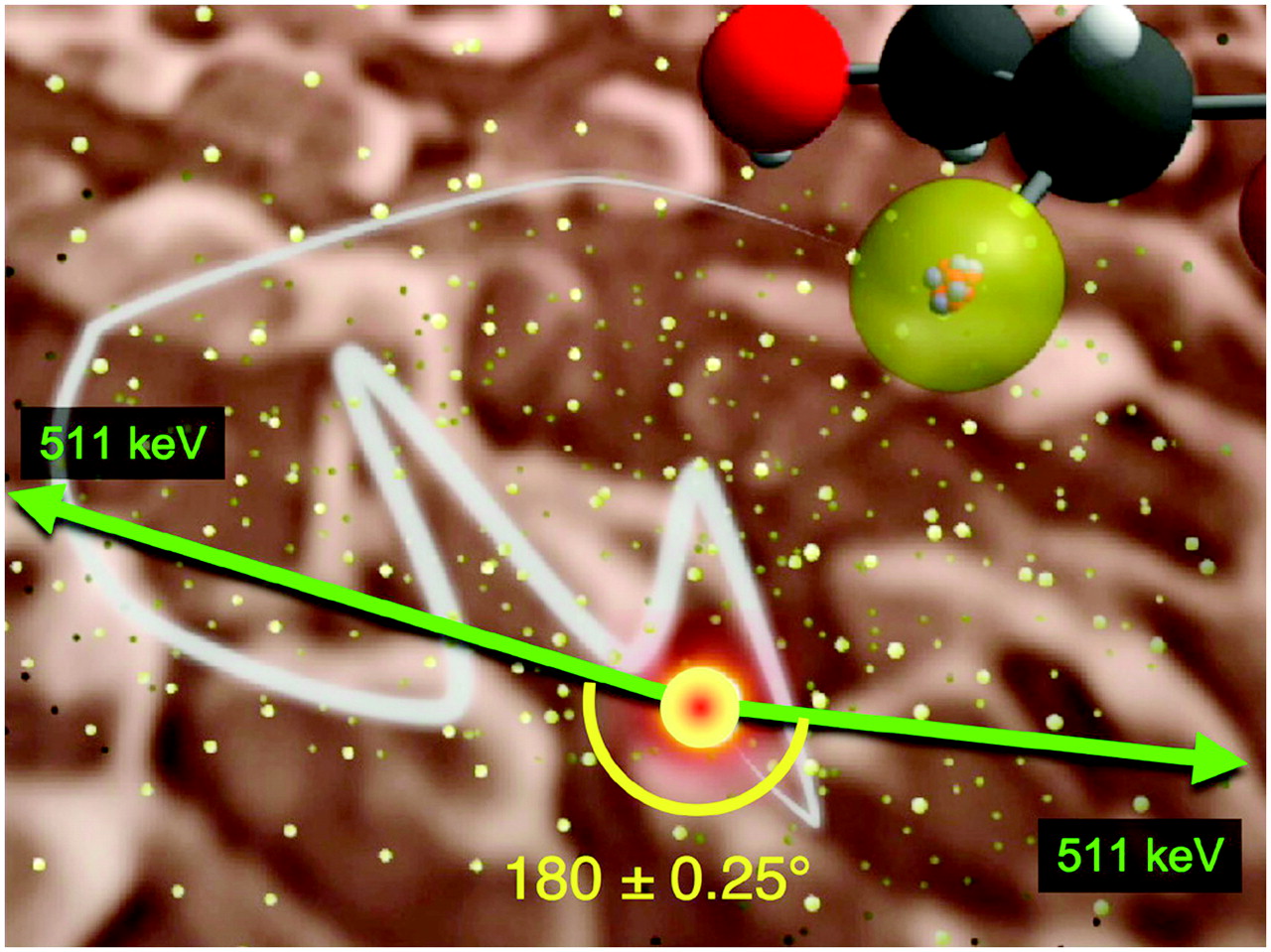
Illustration of non-colinearity of annihilation photons in PET. Angle is greatly exaggerated; distribution of angles around 180° is gaussian, with SD of only 0.25°.
Let us examine how these factors contribute in a typical clinical PET scanner. Assume that the study uses 18F-FDG as the radiotracer, that the scanner has a ring diameter of 80 cm, and that the scanner comprises 2-cm-thick LSO detectors. Figure 5A shows the blurring of a pointlike source of 18F caused by a positron range, non-colinearity, and detector scatter. The convolution of these 3 factors provides an estimate of the limiting resolution (based only on physics) for clinical PET. Note that we are assuming infinitely small detectors and that therefore there is no contribution from the detector size. The result is that we estimate the best resolution achievable to be about 2 mm, in agreement with conventional wisdom. What might be surprising, however, is that this achievement is completely dominated by the non-colinearity effect. Scatter in the detector material and positron range are very small factors.
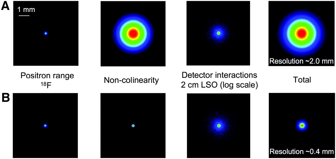
Contribution of physics factors (positron range, non-colinearity, and detector scatter) to resolution attainable in PET: clinical PET scanner, with detector ring diameter of 80 cm, consisting of 2-cm-thick LSO detectors, and imaging radiotracer labeled with 18F (A); small-animal PET scanner, with detector ring diameter of 8 cm, also consisting of 2-cm-thick LSO detectors and imaging 18F-labeled radiotracer (B). Contribution of positron range, non-colinearity, and detector scatter is shown in each case.
Figure 5B shows the same simulation for a small-animal PET scanner, using the same detectors and the same radionuclide, 18F. The only difference is that the detector separation has been reduced to 8 cm, a distance easily sufficient to accommodate a 2-cm-diameter mouse. As Figure 5B shows, this change in geometry has a dramatic effect on the resulting spatial resolution, because the blurring caused by non-colinearity is directly proportional to the detector separation and therefore is reduced by a factor of 10 relative to the clinical scanner. This reduced blurring leads to a predicted limiting resolution of just 0.4 mm. One can also see that the positron range, non-colinearity, and detector scatter effects contribute in a more balanced way to the overall resolution limits and that no single effect dominates.
The next question is how small the detectors in an animal PET scanner need to be in order for the physical detector size not to be a limiting factor and for a spatial resolution close to the predicted 0.4 mm to be reached. It turns out that a detector size of around 0.25 mm is required (36), much smaller than the detectors used in even the latest-generation systems (typically 0.8–1 mm). Thus, there is clearly a potential for much better spatial resolution (roughly a factor of 5 in volumetric resolution) in small-animal PET studies if more finely segmented detectors can be developed. We recently obtained data with 0.5-mm-pixel LSO arrays that produce a spatial resolution of about 0.6 mm (37), indicating that smaller detectors do indeed lead to further improvements in spatial resolution, as predicted. Unfortunately, it is difficult to reliably manufacture scintillator arrays on such a fine pitch—in particular, thick arrays made with scintillators such as LSO and LYSO—and therefore alternatives, such as directly detecting the annihilation photons with relatively dense semiconductor materials such as cadmium telluride, should be pursued. Once such detectors are developed, we can anticipate that the preclinical PET scanners of the future will reach approximately 0.5 mm in spatial resolution, which will open up applications currently out of the range of PET because of resolution limitations, obvious examples being the delineation of several structures in the mouse brain and an improved ability to image early lesions and metastasis in mouse models of cancer.
Although we talk of “limits” of resolution, it should be understood that, in principle, all the physical and geometric factors discussed earlier can be deconvolved, or modeled within iterative reconstruction algorithms, and can be compensated for to a certain extent. Thus, the estimated numbers are not a hard limit but, rather, a limit to what can be achieved without software compensation—bringing us to an issue conspicuous by its absence in this discussion: the subject of sensitivity. To achieve a resolution of 0.5 mm in vivo, and to be able to even contemplate correcting for some of the residual blurring using software approaches, will require a large increase in the number of counts collected in a study. Radiation dosimetry for mouse imaging is not favorable (38), and the molecular targets of interest can easily become saturated if too much mass is injected (39). Therefore, it is not possible simply to inject more radiotracer to get sufficient counts. Rather, large improvements in scanner sensitivity are required. Such improvements are somewhat easier to realize in a small-animal system than in a human scanner, because the animal can almost be surrounded by detectors, without requiring an unreasonable amount of detector material (thus ensuring that almost all photon pairs intersect the detector system). When detectors that measure depth of interaction are used (e.g., (40–42)), thicker detectors (thus ensuring that photons passing through the detectors interact) can be placed close to the animal, reducing the resolution degradation due to parallax errors. Increases in sensitivity on the order of 5- to 10-fold should be possible using a combination of these approaches.
Dual-Modality PET/MRI Scanners
As discussed earlier, PET/CT scanners have become widely adopted in the clinic and now account for most sales of PET scanners. Interestingly, research on another multimodality combination, PET/MRI, started at roughly the same time as PET/CT, in the mid-1990s (43,44). The development of PET/MRI has, however, been much slower, for 2 reasons. First, PET/MRI is technologically more challenging than PET/CT because radiofrequency interference between the 2 imaging systems has to be avoided and the PET detectors must work in relatively high magnetic fields. The fact that most PET detectors are based on photomultiplier tube technology, which is adversely affected by even minimal magnetic fields, poses an immediate problem. But a second difficulty is that, for reasons not completely clear, all developers of PET/MRI systems so far have chosen to position the PET scanner within the magnet of the MRI system to permit simultaneous or near-simultaneous PET and MRI studies, rather than opting for the tandem approach, currently used in PET/CT, in which the 2 scanners are placed next to each other with a common bed. This geometry complicates things much more by creating the additional requirements that the presence of the PET detectors in the magnet not perturb the homogeneity of the magnetic field and that the PET detectors be able to operate in the high fields of the main magnetic field, not just in the fringe field. There are also significant constraints in working in the small space between the gradient coils and the radiofrequency coils within the MRI scanner.
The immediate questions that come to mind regarding PET/MRI are whether it is technically possible and what it will be used for. The earliest motivation for combined PET/MRI was the fact that strong magnetic fields can reduce the positron range effect, discussed earlier, in 2 of the 3 dimensions (43,45,46). Positrons are charged particles and therefore will tend to “spiral” around the magnetic field force lines, reducing their average range before annihilation. However, significant resolution improvements are realized only at high fields (4.7 T or higher) and then only for those positron emitters that emit high-energy positrons. The effect on 18F, and therefore on FDG, is small and not by itself a sufficient motivation for developing combined PET/MRI scanners.
The current motivation appears driven by biomedical applications, both clinical and preclinical. PET/MRI may have advantages over PET/CT in certain applications in which MRI is the anatomic imaging modality of choice, and PET/MRI also has the advantage of reducing the overall radiation dose to the subject by replacing CT with MRI. On the other hand, the use of MRI to compute the attenuation correction for the PET study is not as straightforward (although almost certainly still possible). But it is likely that the major initial use of PET/MRI scanners will be in research, both human and animal. The ability to use PET simultaneously with standard MRI, functional MRI, spectroscopic MRI, and MRI using nanoparticles and targeted contrast agents opens up many interesting possibilities for interrogating a biologic system, some of which may ultimately find clinical translation. Nonetheless, it is fair to say that the applications that are needed to drive the commercial success of PET/MRI are not immediately clear and that a certain assumption of “build it and they will come” underlies much of the research in this area.
Although one can debate how PET/MRI might ultimately be used, there is no doubting the technologic breakthroughs over the past 2 years that are now clearly demonstrating that simultaneous PET/MRI is possible. The earliest attempts at PET/MRI used optical fiber technology to pipe light from scintillators in the bore of a magnet to photomultiplier tubes, with good magnetic field immunity, in the fringe field outside the bore of the magnet (44,47,48). This approach, although successful at producing the first examples of simultaneous PET and MR images, was limited by the low sensitivity and axial coverage of the single-slice PET scanner, and the bulk of optical fibers that needed to be extracted from the magnet prevented any serious thoughts of scaling up the approach for a multiring scanner or for human imaging. The recent surge in interest has been fueled by the availability of avalanche photodiodes (APDs) as a replacement for the magnetic-field–susceptible photomultiplier tube. APDs are light-sensitive detectors that can tolerate high magnetic fields and that perform competitively with photomultiplier-tube–based detectors for PET applications. UC Davis and the University of Tübingen are collaborating on 2 related APD approaches, one using position-sensitive APDs along with short optical fiber coupling (49) and the other using a 3 × 3 array of single-channel APDs without optical fiber coupling (50). Data from both centers already demonstrate the ability to acquire PET and MRI data simultaneously, and for standard anatomic MRI at least, there seems to be no degradation in the performance of either modality. Figure 6 shows a photograph of the completed UC Davis MRI-compatible PET insert, designed to fit inside the bore of a BioSpec 70/30 animal MRI system (Bruker BioSpin). Development of a human PET/MRI scanner for brain imaging is also well under way (51), with plans for extension to a whole-body PET/MRI system. Alternative approaches using novel split magnets, in which the PET detectors reside in the gap between the 2 magnets (52), and a field-cycled MRI system, in which PET data are taken as the magnet is cycled (53), also are under development. From all these efforts, it is now clear that fully functional PET/MRI systems, both for animal and for human applications, will be rolling out over the next 1–3 years, and so the interesting question becomes, What will be the impact of this new technology, and what will be its role in clinical diagnostics, clinical research, molecular imaging, and drug development?
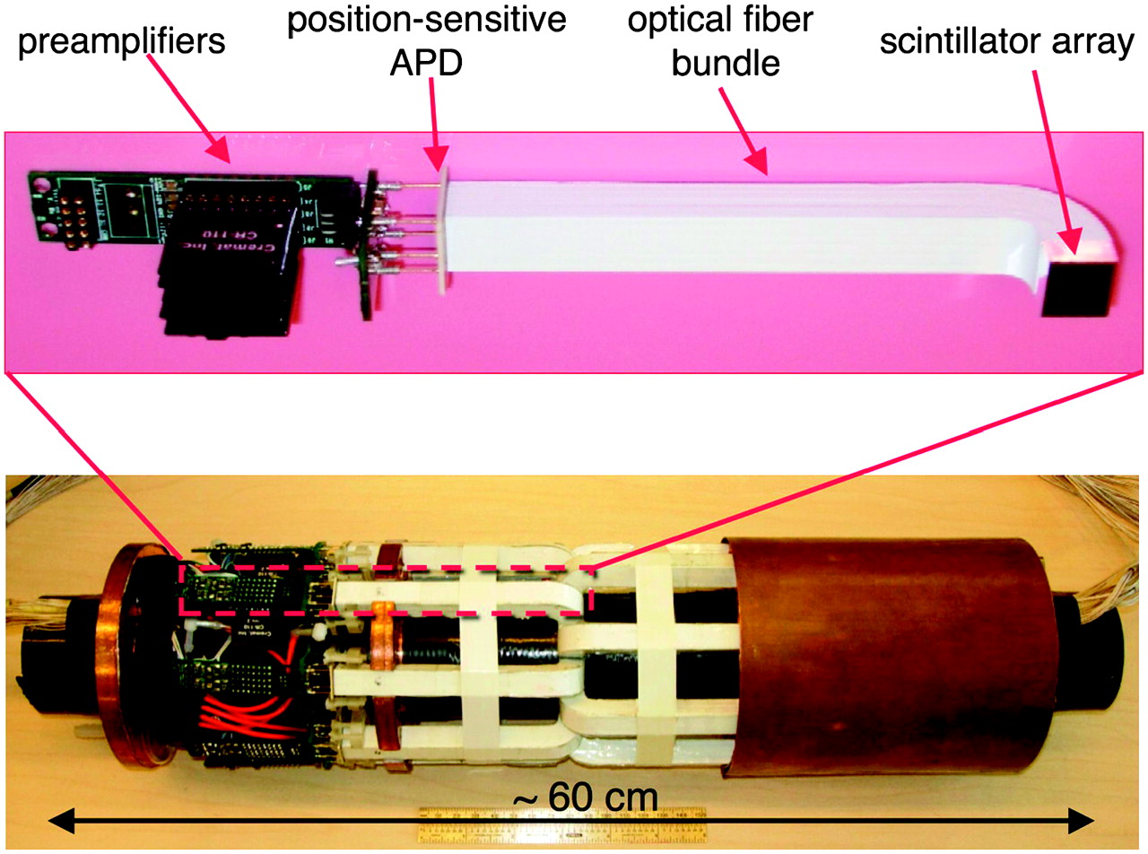
Photograph of MRI-compatible PET insert based on arrays of LSO scintillator coupled through short lengths of optical fibers to position-sensitive APDs and MRI-compatible electronics. This insert fits inside bore of 7-T animal MRI scanner, permitting simultaneous PET and MRI studies.
THE FAR FUTURE: WHOLE-BODY PET/MRI?
If predicting the near future is dangerous, predicting the far future is probably foolish. Nonetheless, it is interesting to speculate what PET instruments might look like some 5–10 years from now. The success of whole-body PET in oncology has demonstrated that PET is well suited to studies of systemic disease and therapies, and thus, one can perhaps anticipate an expanding role for PET in systemic applications such as inflammation, infectious disease, and vascular disease and for the monitoring of systemic therapies, including targeted molecular therapies, cellular therapies, gene therapies, and nanoparticle-based therapies.
Human whole-body PET today is clearly limited by low sensitivity and the resulting low SNR produced in the reconstructed images. Only rarely are studies limited by the resolution of the detectors (typically 4–6 mm) in clinical PET scanners. Thus, breakthroughs in whole-body imaging will require significant increases in sensitivity. At first glance, such increases may not seem easy to achieve; however, some simple calculations perhaps suggest otherwise.
In 3D mode, current scanners have a system sensitivity of roughly 5% at the center of the field of view. That is, 5% of the annihilation photon pairs emitted from a point source at the center of the scanner, in the absence of attenuation and scatter, produce valid coincidence events. When averaged over the entire axial field of view of the scanner, which for the sake of this example we will assume to be 15 cm, the average sensitivity for the portion of the body within the scanner is around 2.5%. Unfortunately, only one eighth or less of the body is in the field of view of our typical clinical scanner at any one time (Fig. 7A). Thus, the effective sensitivity for whole-body imaging is less than about 0.3%! It is also important to point out that these low sensitivities are not principally due to the limited efficiency of the detectors. Typical BGO or LSO detectors with a thickness of 2–3 cm stop on the order of 70%–90% of the 511-keV annihilation photons; thus, relatively little is to be gained by improving the detector efficiency.
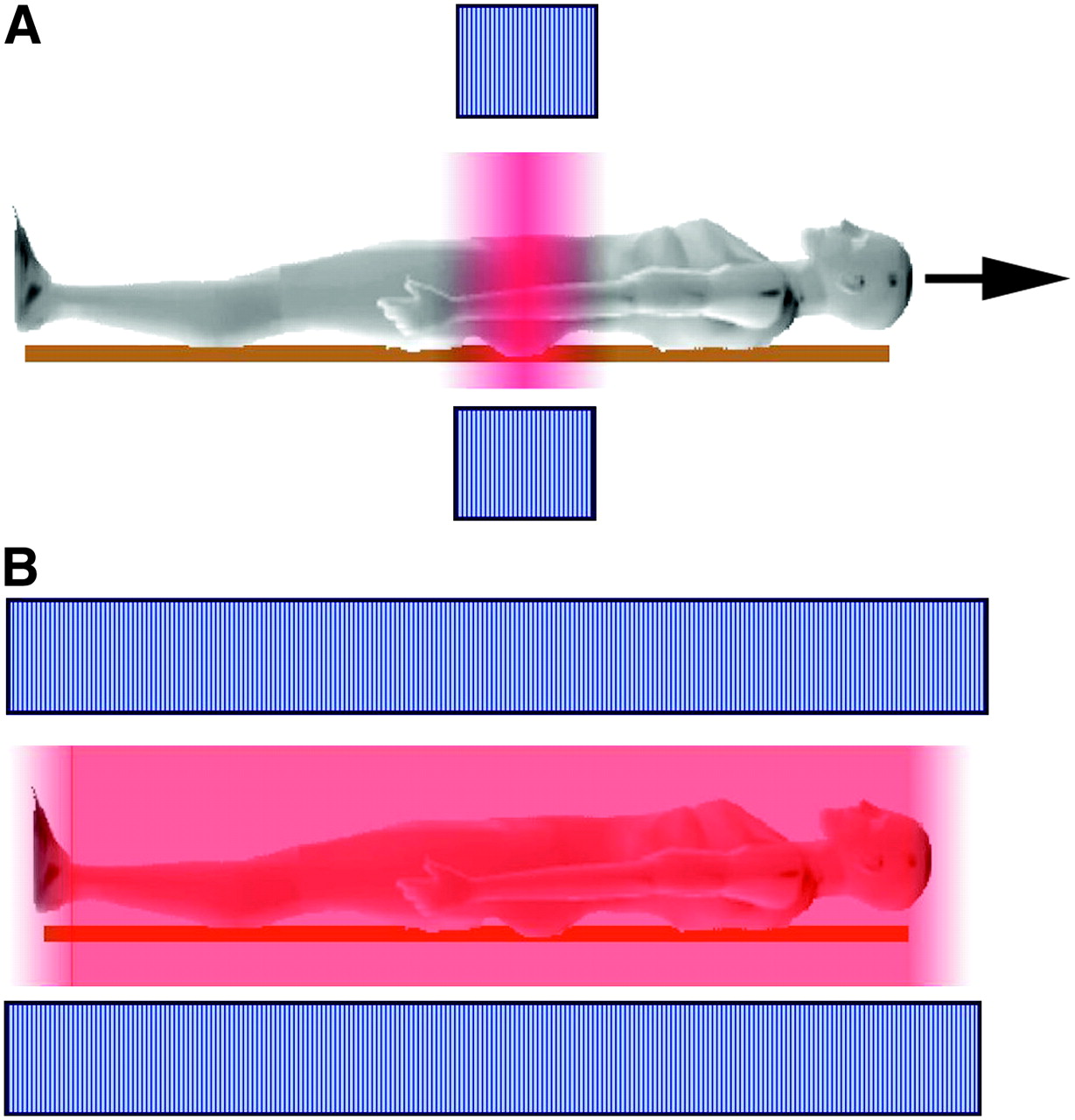
Schematic illustration of current configuration and sensitivity for 3D whole-body PET (A) compared with configuration in which whole body is within field of view (B). Axial extent of PET detectors is indicated by blue, and sensitivity is indicated by the intensity of red.
Large increases in sensitivity can come only by placing much more detector material around the patient, thereby increasing the chance that annihilation photons emitted from the patient actually intersect the detectors. If one conceives of a PET scanner with an axial field of view long enough to contain the whole patient within the scanner (Fig. 7B), the effective sensitivity for imaging the whole body, even if one maintains the same axial acceptance angle, approaches the full 5%. This system sensitivity is roughly an improvement by a factor of 16 with respect to current systems and would improve the SNR in whole-body PET images, all other things being equal, by roughly a factor of 4. If we now add TOF capability to this scanner, another factor of 2–3 is added to SNR, as discussed earlier. So now we have an improvement in SNR that is roughly 1 order of magnitude. And one could argue that this estimate is on the conservative side, because by opening the axial acceptance angle on the large-field-of-view scanner and making the system “fully 3D,” the sensitivity could be increased even more. Simplistically, this kind of increase in SNR allows the PET study to be acquired in one hundredth of the time or with one hundredth of the dose. Alternatively, the increased SNR could be used to improve the spatial resolution of whole-body PET significantly. The trend toward scanners with longer fields of view is already evident, with development of a scanner already having a 68.5-cm axial field of view by Hamamatsu (54), development of LSO panel detectors having a 52-cm axial field of view (55), and simulation studies that examine the performance of scanners with long axial fields of view (56).
Clearly, one would want to integrate this whole-body PET system with high-resolution anatomic imaging, so why not take advantage of the advances in MRI that now permit whole-body imaging to be completed in about 10–20 min and place the entire PET scanner inside a whole-body magnet (Fig. 8)? Imagine the ability to obtain whole-body kinetic studies showing the underlying anatomy, with the obvious applications in whole-body drug pharmacokinetics, dosimetry for radioimmunotherapy, and cell-trafficking studies, and the possibility of implementing quantitative PET tracer kinetic modeling protocols, perhaps even in the clinic, using the left ventricular blood pool as the input function for distant tissues and avoiding the need for arterial blood samples.

Concept of whole-body PET/MRI scanner, and images that such a system might produce (PET image courtesy of Siemens Medical Solutions; whole-body T1-weighted MR image courtesy of Dr. Heinz-Peter Schlemmer, University of Tübingen).
The obvious objection to such a system is one of expense in a financially restricted health care setting. To realize such a system in anything other than an elite medical research environment would require significant reductions in cost. But putting cost aside, technically, it is likely that the PET component of such a system could be built even with current technology, and as outlined here, the combination of PET and MRI is looking increasingly feasible. There are certainly technologic challenges that would need to be addressed to fully realize the kinds of gains in PET that have been suggested. These challenges include the need to control the contribution of scattered coincidences (detectors with excellent energy resolution and perhaps some limited axial collimation) and random coincidences in a scanner that encompasses the whole body, the need for high-speed coincidence electronics to keep up with high data rates, and the need for fast and accurate iterative reconstruction algorithms to provide high-quality images in a reasonable time. But all of these challenges seem within our grasp.
CONCLUSION
Whether this is a reasonable view of the future or a piece of pure science fiction is debatable. Although it is almost certain that this vision of the future will be wrong in many, if not all, of its details, I believe that the spirit of the message will not be wrong and that we will continue to see major advances and improvements in PET technology for some time to come. Clearly, the future will ultimately be determined by the direction that medicine takes and the diagnostic and therapeutic monitoring needs that are generated. The scenario presented here is only one of many possibilities, but generally one can anticipate that an era of targeted molecular, genetic, and immunologic therapies, if it should come to pass, will be good news for nuclear molecular imaging technologies and will provide many opportunities for the further development and effective deployment of our imaging systems. Future advances in PET instrumentation may come from unlikely and unforeseen sources and be driven by applications that are as yet unappreciated or unknown, but they will come.
Acknowledgments
I would first like to thank all the students, staff, and postdoctoral fellows who have worked in my laboratory and inspired me over the years. I specifically acknowledge the work of Ciprian Catana, Dr. Bernd Pichler (PET/MRI scanner), and Dr. Jennifer Stickel (resolution limits in PET) for their research that inspired certain sections of this article.
I want to thank my 3 close faculty colleagues and friends at UC Davis, Dr. Ramsey Badawi, Dr. Jinyi Qi, and Dr. Julie Sutcliffe, for numerous insightful discussions and for helping to create an energetic, enthusiastic, and enjoyable environment for PET imaging research at our institution. I am also deeply grateful to 2 long-time collaborators, Dr. Richard Leahy (USC) and Kanai Shah (Radiation Monitoring Devices Inc.), without whom many of our ideas and interests would never have come to fruition.
I thank my many colleagues throughout academia and industry who have long been helpful and generous, providing advice, suggestions, guidance, and material support. In particular, I acknowledge the many contributions of Dr. Michael Phelps, Dr. Bill Moses, Dr. Joel Karp, Dr. Paul Marsden, Dr. Lars Eriksson, Dr. Robert Nutt, Dr. Ronald Nutt, Dr. Tom Lewellen, Dr. David Townsend, Michael Green, Chris Thompson, Chuck Stearns, James Colsher, and, above all, the late Dr. Edward Hoffman, my mentor for many years.
Support for research originating in our laboratory was generously provided by the Department of Energy, the National Cancer Institute, and the National Institute of Biomedical Imaging and Bioengineering.
Footnotes
-
↵* Based on the presentation given for the Henry Wagner Distinguished Lectureship, 53rd annual meeting of the Society of Nuclear Medicine, San Diego, California, June 2006.
References
- Received for publication August 4, 2006.
- Accepted for publication September 6, 2006.


Jump to section
Related Articles
Cited By...
- Is There a Need for a Pediatric PET/CT Camera?
- Development and Evaluation of mini-EXPLORER: A Long Axial Field-of-View PET Scanner for Nonhuman Primate Imaging
- Total-Body PET: Maximizing Sensitivity to Create New Opportunities for Clinical Research and Patient Care
- A Prototype High-Resolution Small-Animal PET Scanner Dedicated to Mouse Brain Imaging
- Positron emission tomography/computed tomography surveillance in patients with Hodgkin lymphoma in first remission has a low positive predictive value and high costs
- Promising New Photon Detection Concepts for High-Resolution Clinical and Preclinical PET
- Assessing Antibody Pharmacokinetics in Mice with In Vivo Imaging
- Small-Animal Molecular Imaging Methods
- The Advantages of Nanoparticles for PET
- NEMA NU4-2008 Image Quality Performance Report for the microPET Focus 120 and for Various Transmission and Reconstruction Methods
- New Technologies for Human Cancer Imaging
- Noninvasive Imaging of Cell-Mediated Therapy for Treatment of Cancer
- Latest Advances in Molecular Imaging Instrumentation
- PET Image Denoising Using a Synergistic Multiresolution Analysis of Structural (MRI/CT) and Functional Datasets
- Use of a Peptide Derived from Foot-and-Mouth Disease Virus for the Noninvasive Imaging of Human Cancer: Generation and Evaluation of 4-[18F]Fluorobenzoyl A20FMDV2 for In vivo Imaging of Integrin {alpha}v{beta}6 Expression with Positron Emission Tomography