


Abstract
Integrated PET/MRI systems open exciting possibilities for clinical and research applications. However, compared with PET/CT, PET/MRI is a complex technique resulting in new problems and challenges, especially regarding workflow, scan protocols, and data analysis. This complexity applies in particular to examinations in oncology with partial- or whole-body coverage extending over several bed positions. Unlike diagnostic PET/CT, for which the clinical CT protocols can largely be copied from stand-alone CT, the design of a diagnostic MRI protocol for partial- or whole-body coverage is more complex and has to be adapted to the special requirements of PET/MRI to be both time-efficient and comprehensive. Here, we describe basic considerations concerning workflow, imaging protocols, and image analysis for whole-body PET/MRI in oncology, based on our experience with the first integrated PET/MRI scanner. The aim is to fully and optimally make use of the combined PET/MRI measurements in oncology, including identifying and reducing image artifacts as well as optimizing workflow beyond the mere fusion of 2 image datasets.
The success of combined PET and CT has demonstrated the clinical value of multimodality imaging technology, providing both anatomic and molecular information within a single imaging session. However, whereas CT and especially modern multislice CT are a powerful imaging tool, they still have shortcomings, such as low soft-tissue contrast when compared with MRI. Thus, the combination of PET and MRI might be clinically advantageous over PET/CT for some indications. Moreover, because MRI has more potential for functional and molecular imaging than does CT, the combination of PET with MRI offers completely new opportunities for research applications and for molecular imaging in general.
As a consequence, a lot of effort has been put into the development of combined PET and MRI. The first preclinical combined PET/MRI systems were introduced in the 1990s (1–3). Clinically, a PET insert for a standard 3.0-T MRI scanner for simultaneous PET/MRI of the brain (BrainPET; Siemens) was the first successful approach showing the potential of truly simultaneous PET/MRI in the clinical arena (4). Finally, a decade after the commercial introduction of PET/CT, whole-body PET/MRI scanners have now been introduced on the market for clinical use.
There are currently solutions for combined PET and MRI from 3 vendors. GE Healthcare proposes having PET/CT and MRI scanners placed in neighboring rooms, with the ability to shuttle a patient bed between the rooms; each scanner can be used separately as a stand-alone system as well, or they can be used consecutively on the same patient, resulting in a trimodality approach. Philips Healthcare offers a sequential PET/MRI scanner named Ingenuity TF PET/MRI, with PET and MRI scanners being placed beside each other in a single room, and a patient bed capable of rotating 180° being used to transfer the patient from one scanner into the other (5). Siemens Healthcare produces an integrated PET/MRI scanner named Biograph mMR, with the PET detector ring placed within the MRI main magnet using MRI-compatible PET photodetectors (6).
The challenge now is how to exploit the potential of this new modality, which currently represents an expensive diagnostic imaging device. As of today, it is entirely unknown whether PET/MRI will provide incremental diagnostic accuracy, an incremental impact on management, or an incremental impact on patient outcome compared with PET/CT. However, before these questions can be adequately addressed, scan protocols have to be designed that are both time-efficient and comprehensive, as will be discussed in this report. The experience described is based on our work with an integrated system from a single vendor (Biograph mMR). However, the topics and issues described here are expected to be largely applicable to upcoming integrated systems from other vendors as well.
Integrated PET/MRI has raised several major questions, among them the time and cost efficiency of the system—currently an unsolved issue (7,8). In neurologic and, to a lesser extent, cardiologic applications, which might strongly profit from hybrid PET/MRI, this question is usually less complex, as only a single bed position is examined (9,10). The scanning time is then determined by the duration of either the PET or the MRI examination, and there is no need for a second scan in a separate scanner. The time efficiency of integrated PET/MRI is thus evident in this scenario. However, it would be incorrect to assume the same for an oncologic PET/MRI examination, in which an extended body area is usually investigated. Although each bed position in oncologic PET usually requires the same time (e.g., 3 min), this is not necessarily true for MRI, for which different parts of the body might require different MRI sequences and thus a different amount of time to be examined adequately. For advanced molecular imaging applications or MRI spectroscopy, the time needed for the MRI part might be even longer than for routine protocols and might easily exceed 60 min.
This work describes basic considerations for whole-body oncologic PET/MRI using an integrated system in clinical routine, with the aim of helping future users optimize their workflow and imaging protocols. This is a work in progress, and with growing experience the considerations and protocols presented here will need to be continuously adapted and improved.
WORKFLOW AND LOGISTIC CONSIDERATIONS
This section presents some basic but nevertheless important considerations concerning the workflow and logistics that need to be considered before an actual PET/MRI scan is performed. Although such details as patient scheduling, preparation, and positioning may seem like common knowledge, the MRI-related aspects may be of interest to the nuclear medicine community, as may the PET aspects to the radiology community. Physicians and technologists from both communities will encounter new challenges with PET/MRI, compared with standalone MRI, PET, and PET/CT (Table 1).
Technical Aspects and Differences between PET and MRI Relevant for Optimizing Protocols in Integrated PET/MRI
Patient Preparation Before Examination
The patient preparation for PET/MRI will be basically the same as that for a PET or PET/CT examination. In the case of 18F-FDG, this includes prior fasting, control of the glucose level, frequent hydration, and having the patient rest between 18F-FDG administration and imaging to minimize muscle uptake (11,12). For claustrophobic patients, slight sedation such as with low doses of oral benzodiazepines is in our experience needed substantially more often for oncologic PET/MRI than for PET/CT, because of the smaller diameter and longer tunnel of the MRI scanner (13). Potential contraindications to MRI (e.g., non–MRI-compatible pacemakers or artificial heart valves) have to be checked in addition to the usual contraindications to PET, such as pregnancy.
In-Bed Patient Preparation
The patient should be positioned comfortably to minimize motion, with any necessary positioning aids, just as in standalone MRI or PET. What is new compared with standalone MRI is that care has to be taken that any additional positioning aids do not result in significant attenuation of the 511-keV photons (14). In PET/MRI, surface coils are used to increase MRI image quality and reduce imaging time, just as in standalone MRI. However, because the surface coils may cause additional attenuation of the 511-keV photons, only dedicated coils approved for PET/MRI should be used. Patient preparation occurs after 18F-FDG administration and takes substantially longer than for PET/CT and therefore has to be done as quickly as possible by trained personnel to minimize the radiation burden to the staff.
OPTIMIZATION OF PET/MRI PROTOCOLS FOR ONCOLOGIC INDICATIONS
General Aspects
Whole-body PET/MRI protocols all share some common aspects. First, MRI localizers have to be acquired (corresponding to the scout scan or topogram in PET/CT) to plan the subsequent acquisition and, in particular, to define the axial range for the joint PET/MRI examination. PET works in the so-called step-and-shoot mode, in which the 2 main acquisition parameters to be defined are the number of bed positions and the acquisition time for each. In the scanner we used, the axial range of a single bed position is 25.8 cm, with a 6.1-cm overlap between adjacent bed positions. The acquisition time can be kept similar to that in PET/CT, typically 2–4 min per bed position; however, this time can also be increased to make use of the potentially longer interval required for the simultaneous MRI acquisitions. In principle, it is also feasible to acquire PET and MRI data while the patient bed is continuously moving, as recently described for combined PET/MRI (15). This extremely interesting approach might substantially facilitate the workflow for whole-body PET/MRI but is not yet routinely integrated in currently used PET/MRI systems; thus, we will not cover this subject in more detail in this article.
Attenuation data in PET/MRI are derived from the MRI scan (16,17). For each bed position, the MRI sequence for attenuation correction (AC) purposes is acquired first. The sequence used in the integrated PET/MRI system is a 2-point Dixon volume-interpolated breath-hold examination (VIBE). A separate breath-hold acquisition takes place at each bed position, and imaging takes place at a rate of 19 s per bed position. This sequence is preceded by scanning preparations that include shimming to optimize the homogeneity of the magnetic field (∼40 s). The MRI data are then segmented to identify air, lung tissue, fatty tissue, and watery tissue as required for AC (18). The 2-point Dixon VIBE sequence has additionally been found valuable for anatomic localization of PET-positive lesions, as the sequence is acquired over the whole field of view (i.e., all PET bed positions) and is nearly isotropic (19). Other approaches have been suggested for MRI-based AC, such as using a 3-dimensional T1-weighted sequence for a sequential PET/MRI scanner (20), an ultrashort echo time to identify the skull for brain imaging (21), and atlas-based techniques for potential identification of the bones (22).
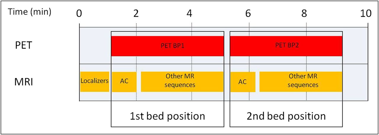
After acquisition of the data for AC, the MRI component can be used to acquire any further sequences within the current field of view, simultaneously with the corresponding PET acquisition, which runs in parallel (Fig. 1). The MRI sequences can also extend beyond the PET acquisition time planned for the current bed position, with the rest of the examination being consequently delayed.

Diagram of basic acquisition protocol covering 2 bed positions in combined PET/MRI. For each PET bed position (4-min acquisition time in example), MRI AC sequence is acquired first and then MRI component can be used for further acquisitions without moving patient bed. BP1 = bed position 1; BP2 = bed position 2.
Potential PET/MRI Protocols for Whole-Body Oncologic Staging
For oncologic PET/MRI, one can envision 2 main scenarios that have important implications for designing the imaging protocol.
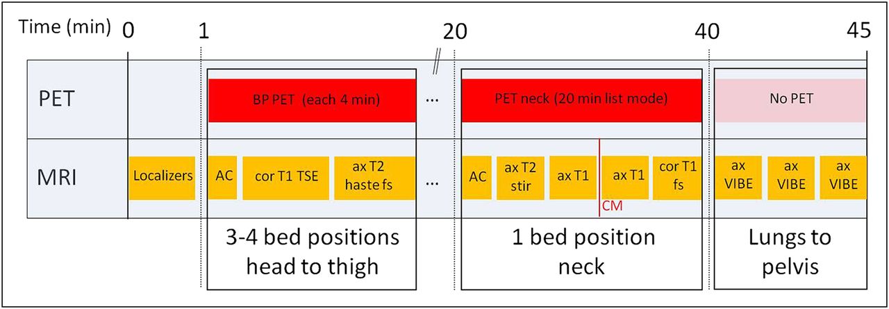
On the one hand, patients may present with prior imaging results, such as a CT scan, and a partial- or whole-body PET/MRI scan of a specific region of interest may be required in addition to the existing imaging data. This scenario might be the case in a colorectal cancer patient in whom a solitary liver metastasis is found on staging CT. In this patient, a resection of the liver metastasis might be indicated, and to complete the staging, MRI of the liver would be requested to rule out further liver lesions and low-dose PET/CT to rule out distant metastases. With PET/MRI, these questions could be answered in a 1-stop-shop examination. In this scenario, the focus of MRI would be only the liver, and a partial-body PET examination with 4–5 bed positions at 2–3 min/bed position could be performed quite quickly. During this time, only the Dixon AC sequence would be acquired (perhaps also an axial fast T2-weighted half-Fourier single-shot turbo spin echo [HASTE] fat-saturated sequence), as previous staging with CT would already be available (Fig. 2). This protocol could be performed within 30 min. The technical parameters of all discussed MRI sequences are presented in detail in Table 2.
Technical Parameters for Different MRI Sequences
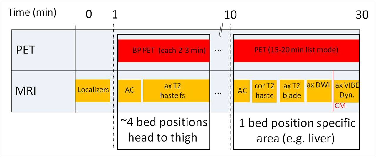
Diagram of acquisition protocol for combined PET/MRI focusing on single area of interest (in this example, liver imaging), with only limited MRI evaluation of partial or whole body. ax = axial; BP = bed position; cor = coronal; CM = contrast medium; DWI = diffusion-weighted imaging; Dyn. = dynamic; fs = fat-saturated.
On the other hand, many patients will present without extensive previous imaging data—for example, during follow-up for evaluation of an increase in tumor markers, to look for metastases or local recurrence. In this case, complete diagnostic coverage of the partial or whole body and specific areas of interest is required. Here, we describe 4 potential protocols for full diagnostic staging in oncology. The protocols cover either the head to the toes (whole body; e.g., for melanoma staging) or the base of the skull to the mid thigh (partial body), comparable to PET/CT, along with specific regions of interest depending on the patient’s diagnosis (e.g., prostate cancer or head-and-neck cancer). Of course, many more protocols or individual variations are feasible, but these protocols encompass most adult oncologic examinations currently performed on the system.
For partial-body examinations, we start with imaging the trunk from the base of the skull to the thigh. Four PET bed positions are usually required, with an acquisition time of about 4 min. This is slightly longer than for the first scenario but gives enough time—after acquisition of the initial breath-hold T1-weighted Dixon VIBE for AC—to obtain both breath-hold coronal T1-weighted TSE and fast axial T2-weighted HASTE fat-saturated dark-blood sequences. Depending on the patient’s compliance and size, this part usually takes about 20–25 min. By this means, T1- and T2-weighted contrast-enhanced sequences are obtained along with 2 planes, allowing both diagnosis of bone metastases and denomination of conditions such as simple cysts or enlarged lymph nodes. Reconstructions of the in-phase image of the Dixon AC sequence in the sagittal and axial planes are done and analyzed in addition to the coronal T1-weighted TSE sequence, with the sagittal view being especially helpful for assessment of bone lesions in the spine.
This initial part of the partial-body examination is followed by imaging of a specific region of interest determined by the clinical question. We obtain a list-mode 15- to 20-min PET scan with simultaneous acquisition of a dedicated MRI scan. For example, patients with head-and-neck cancer or thyroid cancer would undergo dedicated contrast-enhanced MRI of the neck, providing information relevant for local and lymph node staging or for assessment of tumor recurrence, respectively (Figs. 3 and 4) (23). In restaging of prostate cancer with 11C-choline PET, the 15- to 20-min PET acquisition of the pelvis is accompanied by dedicated MRI sequences of this region (Fig. 5). To be more specific, a T2-weighted axial sequence is acquired to provide excellent anatomic detail. Diffusion-weighted imaging and dynamic contrast-enhanced MRI are performed mostly for evaluation of small local recurrences. Recent data imply that dynamic contrast-enhanced MRI is especially valuable for this purpose, as areas of local recurrence usually show early and intense contrast enhancement whereas in later phases scar tissue might also enhance, thus making detection of small tumors in the prostate bed difficult (Fig. 6).

Diagram of acquisition protocol focusing on head-and-neck imaging in combined PET/MRI with full diagnostic coverage of partial or whole body. ax = axial; BP = bed position; cor = coronal; CM = contrast medium; fs = fat-saturated.

Example of head-and-neck imaging in combined PET/MRI (18F-FDG): patient with cancer of oral cavity. (A–C) Coronal T1-weighted turbo spin echo, axial PET, and axial T2-weighted fat-saturated HASTE images show no distant metastases. (D and E) T2-weighted hyperintense lesion on MRI with high glucose metabolism on right side in frontal oral cavity is suggestive of tumor.

Diagram of acquisition protocol focusing on prostate imaging in combined PET/MRI with full diagnostic coverage of partial or whole body. ax = axial; BP = bed position; cor = coronal; CM = contrast medium; fs = fat-saturated.

Example of prostate imaging in combined PET/MRI (11C-choline): patient with radical prostatectomy and PSA recurrence. (A–C) Coronal T1-weighted turbo spin echo, axial PET, and axial T2-weighted fat-saturated HASTE images show no distant metastases. (D) Axial T2-weighted turbo spin echo image provides superb anatomic details of area of former prostate fossa. (E) Dynamic contrast-enhanced MR image shows early intense contrast enhancement in arterial phase. (F) In fused 11C-choline PET image, moderate focal high uptake is found in corresponding region. (G) Parametric map indicating area under curve confirms early and intense enhancement of suspected lesion.
Finally, each protocol includes an axial fat-saturated T1-weighted gradient echo sequence of the whole lung, the abdomen, and the pelvis (e.g., T1-weighted VIBE), each during a single breath hold. Only 5 additional minutes of scanning time are needed, enabling, for example, the evaluation of lung metastases or the better delineation of enlarged lymph nodes, with a CT-like image impression. No PET is acquired during this step. A potential limitation of the described protocols for head-and-neck or prostate cancer is that the liver is imaged only in the venous equilibrium phase, thus making detection of small liver lesions difficult. However, for patients with prostate cancer or thyroid cancer, liver metastases are rare and, when occurring, are usually within the context of diffuse metastatic disease and not single small lesions. In head-and-neck cancer patients, liver metastases can occur despite being relatively rare. The lack of portal–venous contrast-enhanced MRI information about the liver may be compensated for by the available 18F-FDG PET data, which have been demonstrated to be highly sensitive for assessment of metastatic disease, including liver lesions in patients with head-and-neck cancer (24).
For patients with the focus on potential liver metastases, such as from breast cancer, colorectal cancer, or neuroendocrine tumors, we perform dedicated MRI of the liver, including dynamic contrast-enhanced sequences and diffusion-weighted imaging (Figs. 7 and 8). Especially, diffusion-weighted imaging has evolved over the last few years to be a sensitive tool for detection of liver lesions and is superior to 18F-FDG PET for lesions smaller than 1 cm (25). Dynamic contrast-enhanced MRI is also a sensitive method and is useful for lesion classification as well (26). When indicated, central nervous system coverage is performed with axial fluid-attenuated inversion recovery and contrast-enhanced T1-weighted sequences. In addition, in this patient group axial fat-saturated T1-weighted gradient echo sequences are acquired, each during a single breath-hold (e.g., T1-weighted VIBE), as described above.

Diagram of acquisition protocol focusing on liver imaging in combined PET/MRI with full diagnostic coverage of partial or whole body. ax = axial; BP = bed position; cor = coronal; CM = contrast medium; DWI = diffusion-weighted imaging; Dyn. = dynamic; fs = fat-saturated.

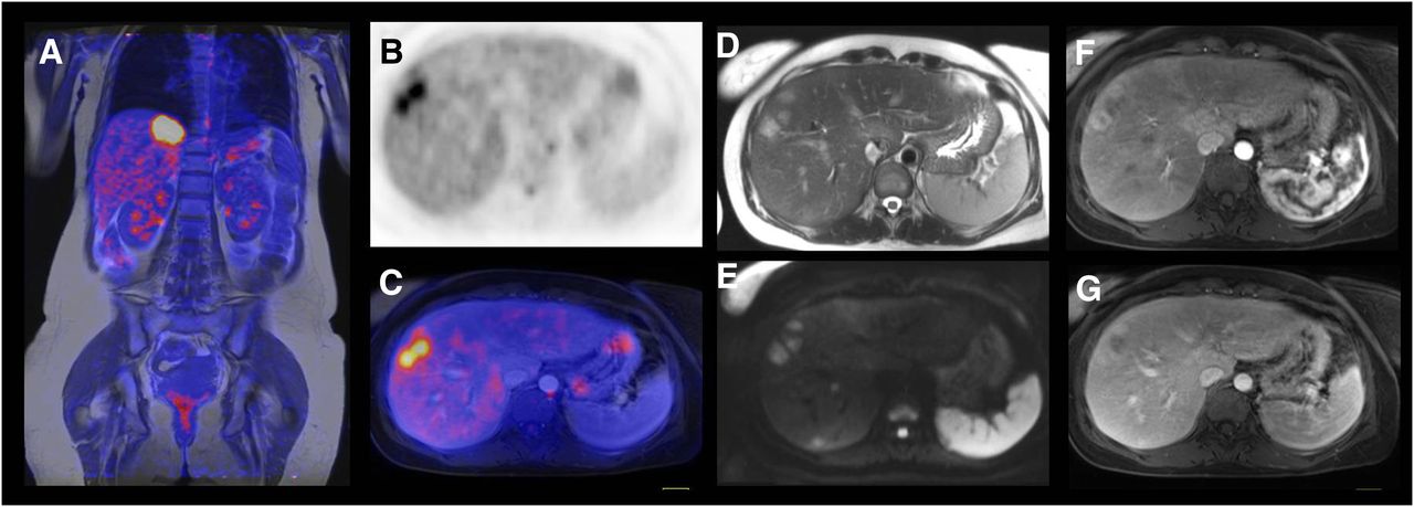
Example of liver imaging in combined PET/MRI (18F-FDG): patient with breast cancer and liver metastases. (A) Fused coronal T1-weighted turbo spin echo image with PET image shows hypermetabolic lesion in liver below medial part of diaphragm. (B and C) Axial PET image and axial fused image outline 2 adjacent liver metastases in right lobe. (D–G) Axial morphologic MR images (T2-weighted HASTE [D], diffusion-weighted [E], dynamic contrast-enhanced [F and G]) demonstrate high soft-tissue contrast on MRI and superb anatomic delineation of liver metastases.
For certain indications, true whole-body coverage from head to toe or assessment of the central nervous system is mandatory, as for example, in melanoma patients or lung cancer patients. In these cases, we use a protocol with about 4 bed positions of 4 min each covering the torso and 3–5 additional bed positions of 2 min each covering the legs, depending on the size of the patient. During this time, coronal short-τ inversion recovery sequences (or T1-weighted SE sequences) can be acquired simultaneously during the PET acquisition. For melanoma or tumors known to metastasize in unusual patterns, we prefer short-τ inversion recovery in this protocol as it better highlights soft-tissue lesions such as small lymph nodes or cutaneous lesions. Subsequently, MRI is performed only for liver, lung, and central nervous system coverage (Figs. 9 and 10). This protocol is, however, more time-consuming and requires about 60 min of scanning time (depending on the size and compliance of the patient), despite the advantage of having an integrated system.
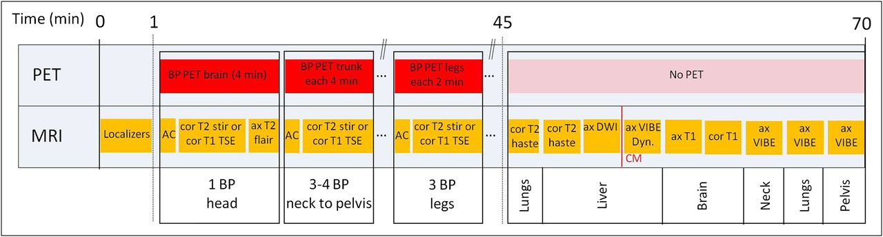
Diagram of fully diagnostic whole-body acquisition protocol in combined PET/MRI. ax = axial; BP = bed position; cor = coronal; CM = contrast medium; DWI = diffusion-weighted imaging; Dyn. = dynamic; fs = fat-saturated; stir = short-τ inversion recovery.
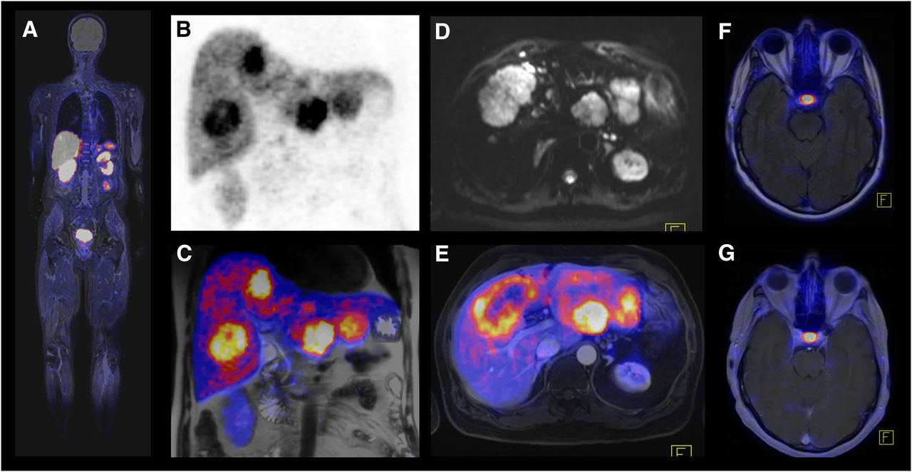
Example of whole-body imaging in combined PET/MRI (68Ga-DOTATOC): patient with neuroendocrine cancer and liver metastases. (A) Fused coronal T2-weighted short-τ inversion recovery and PET images demonstrate whole extent of examination. Because of incomplete coverage of lower legs by total-imaging-matrix surface coils, intensity and quality of MRI images in this area are substantially reduced. (B and C) PET and fused images show multiple liver metastases with high somatostatin receptor expression. (D) Diffusion-weighted image (with b-value of 50 s/mm2) shows large metastasis with many surrounding small lesions. (E) In comparison to diffusion-weighted image, fused axial T2-weighted fat-saturated HASTE and PET image demonstrates that small lesions are not visible on PET. (F and G) Fused axial T2-weighted fluid-attenuated inversion recovery image and axial T1-weighted gadolinium-enhanced image show physiologic uptake of hypophysis and no evidence of brain metastases.
In the system we used, the total-imaging-matrix surface coils do not cover the entire body in a normal-sized adult, and images of the lower legs are therefore not of optimal quality. If images of this area are of clinical relevance, the patient can be repositioned with feet first in the scanner to cover the lower legs with surface coils.
As a general diagnostic limitation of all the mentioned protocols, the inferiority of conventional MRI, in comparison with CT, for detecting small pulmonary nodules and assessing subtle parenchymal changes should be kept in mind. More specific MRI protocols in addition to the sequences described above, such as respiration-triggered or gated MRI sequences, can be included. However, these protocols may be time-consuming and probably can be efficiently applied only for specific lung-evaluation indications (currently under investigation). Alternatively, an unenhanced low-dose CT scan of the lungs might be added until systematic studies have addressed in more detail the performance of PET/MRI for evaluation of small lung metastases.
Data Visualization and Analysis
An unprecedentedly large number of images are generated in a hybrid PET/MRI examination, which—depending on the protocol—can generate more than 10,000 slices. As in the reading of PET/CT along with diagnostic CT, joint reading of PET/MRI by physicians from both specialties or by double-trained physicians is necessary, including those with subspecialties such as neuroradiology or pediatric radiology for certain indications. As for image analysis, there is no single strategy or algorithm for reading PET/MRI data, and every institution has to define its own way of doing so. However, some recommendations and suggestions for a potential reading workflow will be discussed here, with a focus on the special requirements of PET/MRI data as compared with PET/CT data.
One basic difference between PET/MRI and PET/CT is that more than a single PET dataset might be available. For example, there may be a whole-body PET dataset acquired at 2–4 min per bed position, along with a separate PET bed position of 15–20 min covering a special region of interest (head and neck, prostate, liver, or another region). A further difference is that there exist a multitude of different anatomic datasets, not all of which would necessarily cover the whole field of view or be isotropic, as opposed to modern multislice PET/CT data.
For interpretation of PET/MRI images, the PET data from the partial- or whole-body coverage are first fused with anatomic data, and a maximum-intensity projection of the PET data is created, just as in PET/CT. In a first navigation step, the Dixon AC sequence is used for image fusion: although its low resolution limits its diagnostic value, the advantage of near-isotropic coverage of the whole field of view is useful for a quick overview and for localization of PET-positive lesions. Subsequently, for a more detailed analysis, the T1-weighted coronal data and the HASTE T2-weighted fat-saturated axial data are then used for fusion with the whole-body PET images in the coronal and axial planes, respectively. These data are, however, not isotropic and thus are useful only in their primary orientation. They then can be compared side by side with the axial contrast-enhanced T1-weighted VIBE fat-saturated images for a complete analysis of the whole body. Afterward, the dedicated PET images of the area of interest, acquired for a longer time, can be fused with an anatomic dataset of this area and analyzed side by side with the other MRI sequences of the area.
It is even more important than in PET/CT that the non–attenuation-corrected images be evaluated during clinical reading of the PET images to recognize attenuation-related artifacts and to evaluate the lungs. In contrast to PET/CT, in PET/MRI it is mandatory that the MRI-based attenuation map (or μ-map) be checked for any attenuation-related artifacts. The most common of these in PET/MRI are described in the following section.
Possible Artifacts in PET/MRI
The MRI component of a PET/MRI scanner should perform similarly to a standalone MRI scanner; thus, no particular artifacts are expected for the MRI part of the examination. However, the PET images can show artifacts resulting mainly from the use of MRI-based AC. Therefore, the artifacts in PET/MRI could differ from those in PET/CT.
Metals
Metallic implants produce a local signal loss in MRI images, misleading the image segmentation procedure and resulting in classification of the region as air instead of tissue in the MRI-based attenuation map. This misclassification may result in severely underestimated uptake in the region surrounding the metallic implant (Fig. 11). The artifact differs from that observed in PET/CT, where metal usually leads to artificially increased uptake.
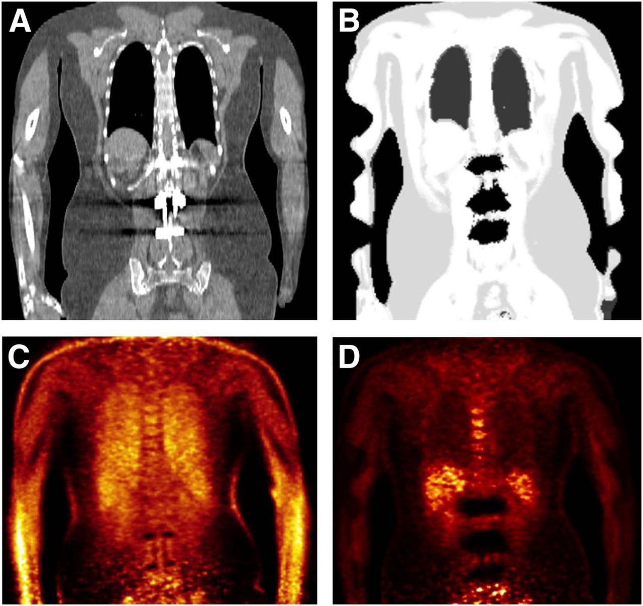
Patient with metallic implants from lumbar spine surgery. Metallic artifacts in CT image (A) result in region’s being incorrectly segmented as air in MRI-based attenuation map (B). Non-AC PET image (C) shows normal tracer distribution around implants, but MRI-based AC leads to large areas of underestimated uptake (D).
Truncation
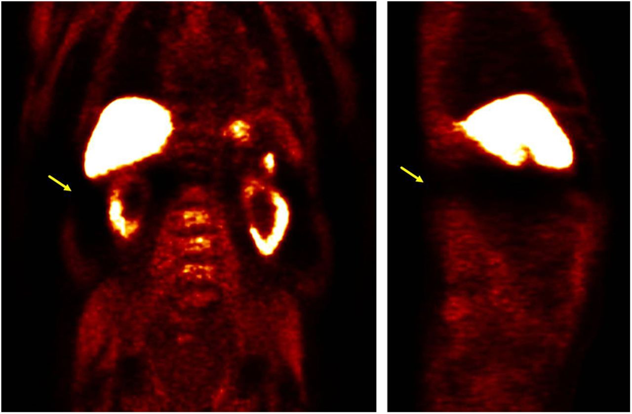
Whereas the PET field of view is almost 60 cm, the MRI field of view is only around 45 cm because the inhomogeneity of the magnetic field rolls off toward the edges of the bore. This limited field of view results in truncated parts of the body in MRI images in general and in the MRI-derived attenuation map in particular. If the patient is examined arms-up, truncation artifacts may occasionally be seen in the shoulders, breasts, abdomen, or hips. If the patient is examined arms-down, the arms of nearly all patients will be severely truncated in the images. A truncated attenuation map affects the PET image both through the AC and through the scatter correction (27,28). In our experience so far, the most noticeable effect is an anterior–posterior gradient in the liver for 18F-FDG images (Fig. 12). Also, the quantification of the standardized uptake value of a lesion might be affected. For other tracers with stronger physiologic uptake in organs such as the liver or spleen (e.g., 11C-choline or 68Ga-DOTATOC), the resulting artifact may occasionally be much harsher because of its impact on scatter correction, occasionally rendering the entire region near the respective organ unevaluable (Fig. 13), an effect that disappears for reconstructions without scatter correction, but at the price of losing the means of quantification. Techniques to recover the truncated part of the field of view have been developed (29,30), and in the system we used it is possible to apply the PET emission data to roughly estimate the cropped part of the attenuation map. Such techniques might be helpful to minimize these artifacts, but further investigation and validation are still needed.

MRI-based attenuation map (top row) and corresponding 18F-FDG PET images (bottom row) acquired arms-down showing truncation in arms and resulting artifacts: inhomogeneity in liver (anterior–posterior gradient, yellow arrows) and sharp change in uptake in arms corresponding to limit of field of view (blue arrows).
Severe artifacts in 11C-choline PET images acquired arms-down. Truncation of attenuation map can occasionally lead to biased scatter correction, which renders complete regions unevaluable (yellow arrows).
PET/MRI Misregistration
Misregistration between the PET emission data and the attenuation map is known to cause artifacts in the PET attenuation-corrected images (31,32). In PET/MRI, simultaneous acquisition helps reduce the frequency of misregistration as compared with PET/CT, but misregistration artifacts are still occasionally present, mainly because of differences in the respiratory state. The attenuation sequence should be acquired in end expiration to achieve better alignment (31).
Lowered Uptake in Bone
Current methods for AC in PET/MRI ignore the specific contribution to attenuation by cortical bone. Consequently, decreased uptake is expected when MRI-based AC in used for images of massive bony structures (e.g., pelvis, spine, or femur) and their vicinity. Different groups evaluating MRI-based AC have reported maximum errors of up to 13% (18,20) or 17% (33) in the standardized uptake value of bony structures, but such errors should not greatly affect the diagnostic value of the technique.
Nonrecognition of Lung Compartment
The 2-point Dixon approach currently recognizes the lungs by a closed-component algorithm that detects the largest air-filled cavities and assigns to them the attenuation value for lung tissue. However, one or both lungs are occasionally not identified correctly and instead are interpreted as air, thus leading to undercorrection of standardized uptake values in this area. The possibility of this artifact can be assessed by referring to the attenuation map and the non-AC images. This approach is also useful for identifying the effects of contrast agents, which tend to produce extended contours.
CONCLUSION
Integrated PET/MRI systems allow simultaneous acquisition of PET and MRI data. Based on our initial experience over 1 y, the described considerations concerning workflow, imaging protocols, and data analysis show that the planning, execution, and analysis of whole-body PET/MRI in oncology can be quite time-consuming and complex. To guarantee a clinically valuable, time- and cost-efficient use of PET/MRI in oncology, it is mandatory that the indications be chosen correctly, that cross modality training be performed, that the acquisition protocols be optimized, and that the images be carefully reviewed, taking into account potential artifacts. However, if these points are respected, it is possible to perform high-quality whole-body PET/MRI in a reasonable time, giving the technique great potential for use in many indications in oncology.
Footnotes
Published online Aug. 9, 2012.
↵* Contributed equally to this work.
Learning Objectives: On successful completion of this activity, participants should be able to describe (1) special requirements for planning whole-body PET/MRI examinations; (2) general aspects of whole-body PET/MRI protocols in oncology; and (3) possible artifacts in PET/MRI.
Financial Disclosure: An author of this article is a meeting participant or lecturer for Siemens AG. No other relevant relationships that could be perceived as a real or apparent conflict of interest were reported.
CME Credit: SNMMI is accredited by the Accreditation Council for Continuing Medical Education (ACCME) to sponsor continuing education for physicians. SNMMI designates each JNM continuing education article for a maximum of 2.0 AMA PRA Category 1 Credit. Physicians should claim only credit commensurate with the extent of their participation in the activity. For CE credit, participants can access this activity through the SNMMI Web site (http://www.snmmi.org/ce_online) through September 2013.
- © 2012 by the Society of Nuclear Medicine and Molecular Imaging, Inc.
REFERENCES
- Received for publication May 28, 2012.
- Accepted for publication July 20, 2012.


Jump to section
Related Articles
Cited By...
- Concurrent Respiratory Motion Correction of Abdominal PET and Dynamic Contrast-Enhanced-MRI Using a Compressed Sensing Approach
- New Approaches to Molecular Imaging of Multiple Myeloma
- Techniques, Benefits, and Challenges of PET-MR
- Motion Correction Strategies for Integrated PET/MR
- Diagnostic Value of Diffusion-Weighted Imaging in Simultaneous 18F-FDG PET/MR Imaging for Whole-Body Staging of Women with Pelvic Malignancies
- Radiotracer Dose Reduction in Integrated PET/MR: Implications from National Electrical Manufacturers Association Phantom Studies
- Workflow Considerations in PET/MR Imaging
- Principles of PET/MR Imaging
- Performance of Whole-Body Integrated 18F-FDG PET/MR in Comparison to PET/CT for Evaluation of Malignant Bone Lesions
- Implementation and Performance Evaluation of Simultaneous PET/MR Whole-Body Imaging with Continuous Table Motion
- Monocyte-Directed RNAi Targeting CCR2 Improves Infarct Healing in Atherosclerosis-Prone Mice
- PET and MR Imaging: The Odd Couple or a Match Made in Heaven?