


Abstract
Artifacts related to metallic implants are an established limitation of CT-based attenuation correction (CT-AC) in PET/CT. However, the impact of metallic components of pacemaker leads and implantable cardioverter defibrillator (ICD) leads on the accuracy of cardiac PET has not been evaluated. The goal of this study was to investigate the magnitude of artifacts related to pacing and defibrillation leads in both phantom and patient studies. Methods: Images were acquired on a PET/CT scanner using CT-AC and were compared with those obtained on a dedicated PET scanner using transmission source-based attenuation correction. Phantoms consisting of pacemaker leads and ICD leads submerged in uniform background activity solution were imaged, and regions were analyzed to measure radionuclide concentrations at known lead locations relative to background. In addition, 15 cardiac 18F-FDG patients (having either pacing leads, defibrillation leads, or both) were imaged on both PET/CT and PET scanners. Images were visually and quantitatively assessed to determine whether artifact related to the implanted leads was present and, if so, its severity relative to surrounding myocardium. Results: In phantom studies, artifacts caused by pacing lead electrodes were barely noticeable, but artifacts arising from highly radioopaque ICD shock coil electrodes were clearly apparent. In the patient studies, no artifacts from pacing leads were identified. However, significant artifact was observed in 50% of the patient studies with ICD leads. In the affected areas, local myocardial uptake in PET/CT images using CT-AC was, on average, 30% higher than that in the corresponding PET images. Conclusion: Although pacemaker leads do not appear to cause artifact in cardiac PET/CT images, ICD leads frequently do result in artifacts of sufficient magnitude to impact clinical image interpretation. Accordingly, software-based corrections in CT-AC algorithms appear necessary for accurate cardiac imaging with PET/CT.
Myocardial perfusion and metabolic imaging with PET is well established in clinical nuclear cardiology (1,2). In recent years, hybrid systems combining a PET scanner with a CT scanner have become available commercially (3). The advantages of combined anatomic and functional imaging are widely accepted for whole-body oncology imaging (4–7). As a consequence, the market share of PET/CT has grown significantly, such that PET/CT devices now constitute a large majority of all new PET scanners purchased (8).
A fundamental difference between PET/CT and dedicated PET is the use of CT images for PET attenuation correction (9). Significantly shorter scan times associated with CT-based attenuation correction (CT-AC) are an advantage of PET/CT, especially for whole-body oncology studies. However, a disadvantage of CT-AC is overcorrection associated with iodinated or barium-based contrast agents and metallic implants, due to the energy-dependent extrapolation of the attenuation coefficients (10–13). PET radionuclides emit 511-keV γ-rays via positron decay, whereas x-rays with lower energies, mainly ranging from 40 to 100 keV and with average energy near 60 keV, are used with CT. CT-derived attenuation coefficients therefore must be rescaled when they are converted into PET attenuation maps (14). Most metals and contrast agents exhibit strong photoelectric absorption of x-rays but, like bone and other tissues, interact with 511-keV γ-rays primarily via Compton scattering. The CT-AC scaling algorithm does not account for this effect and causes overcorrection of PET images. In contrast, conventional dedicated PET scanners use 68Ge/68Ga or 137Cs transmission sources emitting γ-rays with energies of 511 and 662 keV, respectively. As a result, overcorrection from metallic implants is not a significant issue for dedicated PET.
In cardiac PET/CT, artifacts might arise similarly from metallic components of pacemaker leads or implantable cardioverter defibrillator (ICD) leads near the myocardium and pose an even more significant problem than in oncology. Because interpretation of PET perfusion and metabolic images involves the assessment of relative uptake in all regions of the myocardium (often using quantitative analysis software), accurate attenuation correction is critical. Overcorrection from CT-AC due to these metallic implants might therefore affect interpretation if not recognized or corrected.
The goal of this investigation was to determine the magnitude of artifact arising from metallic pacing and defibrillation leads in cardiac PET/CT. Phantom and patient studies were acquired on both a PET/CT scanner using CT-AC and a dedicated PET scanner using transmission sources, allowing direct comparison of image sets susceptible or not susceptible to metal-related artifact.
MATERIALS AND METHODS
PET/CT scans were performed on a Siemens Biograph16 system. The PET portion of the system consists of 24 rings with a total of 9,216 lutetium oxyorthosilicate (LSO) crystals of dimensions 6.45 × 6.45 × 25 mm. The PET scanner contains “PICO” detector electronics with 4.5-ns coincidence resolving time and 400- to 650-keV energy window, has an axial field of view of 162 mm, and operates in fully 3-dimensional (3D) mode without septa. The CT portion of the system consists of a 16-row ceramic detector with 1,344 channels per row and adaptive collimation. Rotation rates from 0.5 to 1.5 s per rotation are supported. CT-AC of PET data utilizes the scaling algorithm published by Kinahan et al. (9).
PET scans were also performed on a Siemens ECAT HR+ scanner. The PET detectors consist of 32 rings with a total of 18,432 bismuth germanate (BGO) crystals of dimensions 4.05 × 4.39 × 30 mm. The detector electronics have 12-ns coincidence resolving time, 350- to 650-keV energy window, and an axial field of view of 155 mm. The scanner can operate in either 2-dimensional mode with septa or fully 3D mode without septa; however, all scans in this study were done in 3D mode to parallel the PET/CT characteristics. The scanner employs 3 rotating 68Ge/68Ga transmission rod sources, each of 111-MBq (3 mCi) nominal activity for attenuation correction.
Phantom Studies
Phantom studies of pacing leads and ICD leads in uniform background activity were acquired on both scanners. In 2 separate studies, 3 pacemaker leads (Medtronic, Inc. and Cardiac Control Systems, Inc.) or 2 ICD leads (St. Jude Medical, Inc. and Medtronic, Inc.) were placed in a 30 × 22 cm elliptic tank phantom (Data Spectrum, Inc.) containing 37 MBq (1.0 mCi) of 18F-FDG in 8.8 L solution. The tips of the leads were oriented so that the electrodes were parallel to the axial slice plane, to maximize the degree of in-slice artifact. On the HR+ PET scanner, 8 min of emission data were acquired followed by 5 min of transmission data. Images were reconstructed with the following parameters: 128 × 128 matrix, Fourier rebinning, iterative algorithm (order-subsets expectation maximization), 4 iterations, 8 subsets, 6-mm gaussian postfilter, 1.5× zoom (pixel size, 3.5 mm), nonsegmented transmission attenuation correction, randoms correction (online subtraction), and scatter correction (ECAT v7.2.1).
On the Biograph PET/CT scanner, an 8-min emission data acquisition was preceded by a CT acquisition, which was used for attenuation correction and for localization of the lead electrodes. The CT acquisition was a low-dose 42-s CT acquisition using the following parameters: 120 kVp, 92 mAs (minimal setting on Biograph), 1.5-s rotation, 6.4 mm per rotation table feed, 16 × 0.75 mm collimation, and 5-mm slice thickness. This “slow” CT acquisition protocol (15) is designed to avoid breathing-related artifacts from CT-AC in patient studies and is performed under free breathing conditions to average out respiratory motion (16). PET/CT images were reconstructed with identical parameters as for the dedicated PET images, with the exceptions of CT-AC and different version scatter correction algorithm (Biograph v3.1).
Patient Studies
Fifteen patients with implanted cardiac leads (5 with pacing leads only, 5 with defibrillation leads only, 5 with both pacing leads and defibrillation leads) undergoing clinical cardiac metabolic imaging with 18F-FDG on the HR+ PET scanner were recruited for an additional scan on the Biograph PET/CT scanner. The study protocol and patient consent form were approved by the Cleveland Clinic Foundation’s Institutional Review Board. After a nominal 260-MBq (7 mCi) injection of 18F-FDG and 45-min uptake time, PET images were acquired as follows: a 2-min preview emission scan to localize the heart in the field of view, followed by a 50-million count (trues) emission in 3D mode, followed by a 40-million count (trues) transmission scan. Within 30 min after their PET acquisitions, patients were scanned on the Biograph PET/CT scanner. After a planning topogram, a low-dose slow CT acquisition (as above) was performed under free breathing conditions to generate the CT images for the purpose of attenuation correction. After the CT, PET emission data were acquired for 10 min in list mode and histogrammed into sinograms afterward. The PET/CT images were reconstructed in an identical fashion as that of the phantom studies.
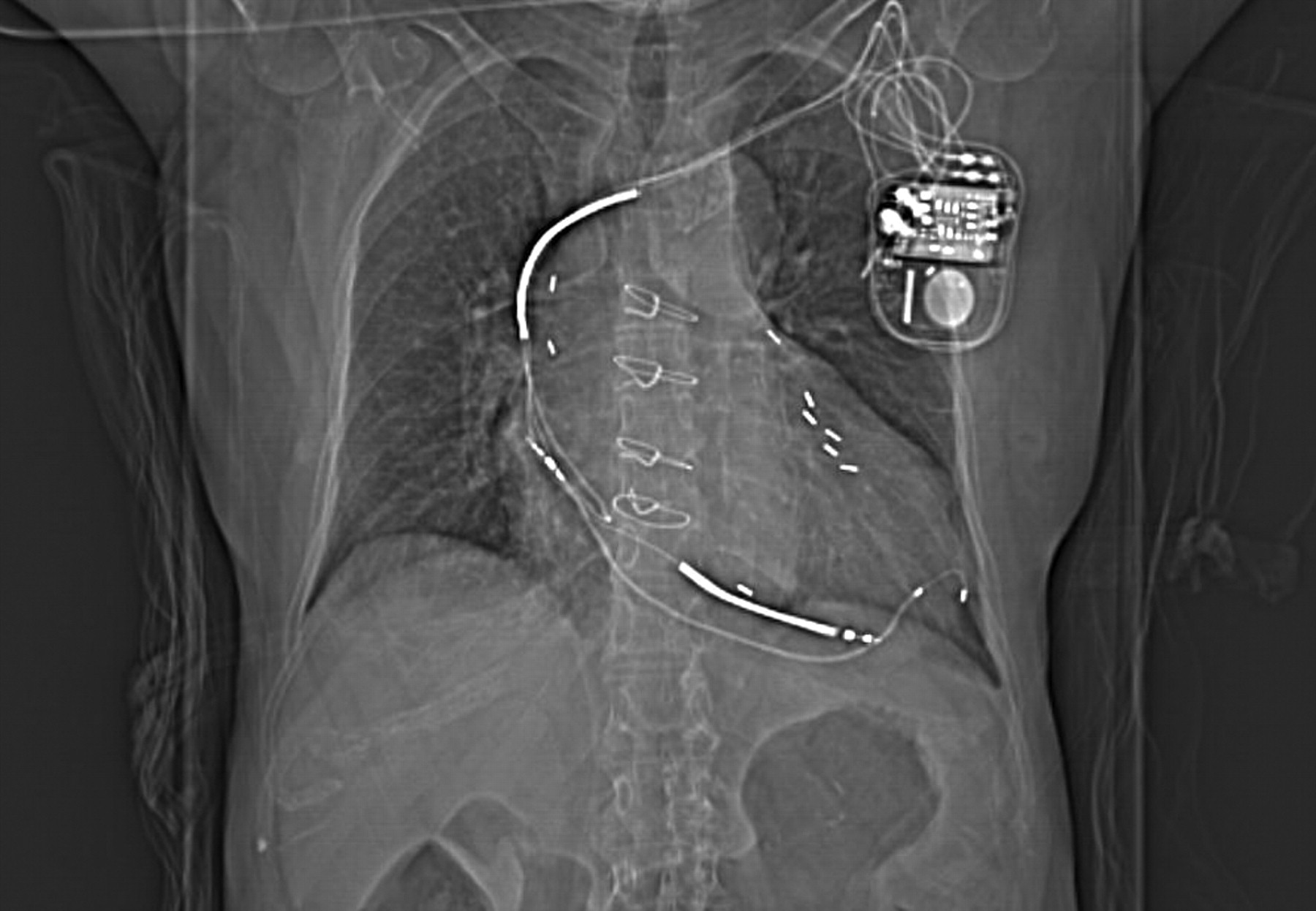
Images were analyzed both qualitatively and quantitatively to estimate the degree of metal-related artifact. The phantom images from both scanners, including the transmission images, were visually assessed for the presence or absence of artifact. Afterward, using coregistered CT images as a guide, regions of interest were placed over the known electrode locations, and average count densities were obtained and compared. For the patient studies, the planning topogram (Fig. 1) and CT images were viewed to determine the type of lead(s) and implant location(s). The relative size of CT artifacts was measured from the derived attenuation maps as the integral of the attenuation coefficient over the artifact volume, after identifying the artifact boundaries and after subtracting the mean attenuation coefficient of surrounding tissues. PET images from both scanners were reoriented along standard cardiac axes (short axis, horizontal long axis, vertical long axis) using a Siemens e.soft 3.5 workstation, while carefully matching the orientations of paired images from each patient. Polar maps of the PET images also were generated using the 4DMSPECT (University of Michigan) analysis program. On the short-axis slices of the fused PET/CT images, the average distance from the ICD shock coil to the left ventricular wall was measured. Images and polar maps from both scanners were compared, and a visual determination was made as to whether metal-related artifact was present. The magnitude of artifact was measured as the peak-to-background ratio from circumferential polar map plots, with the background level determined by interpolation of neighboring regions.

Topogram image of patient study shows ICD/pacing device, ICD lead with dual shock coils, and pacing lead with electrodes implanted in left ventricle. Sternal wires and surgical clips are visible from prior surgical procedure.
RESULTS
Phantom Studies
Phantom images with pacing leads and defibrillation leads from both the PET/CT and PET scanners were analyzed. The locations of the leads were apparent from the fused PET and CT images. Image coregistration was automatic for the Biograph PET/CT data, whereas transmission and emission images from the HR+ scanner were coregistered to CT images by software fusion (Siemens Syngo 3D software).
Representative CT, transmission, and PET image slices illustrating the magnitude of artifact resulting from the metallic lead electrodes are shown in Figure 2. The electrodes produced intense artifacts and streaking in the CT images, resulting in regions of very high and low Hounsfield numbers. The shock coils of the ICD leads caused significantly larger CT artifacts than the smaller pacing lead electrodes. The central lead wires were also visible on the CT images, but they did not cause much artifact or streaking, being less dense than the electrodes. In contrast, there were no significant artifacts on the ECAT HR+ 68Ge transmission images. The transmission images appeared relatively uniform in relation to the noise level, and no regions of higher attenuation were observed corresponding to the known locations of the leads.
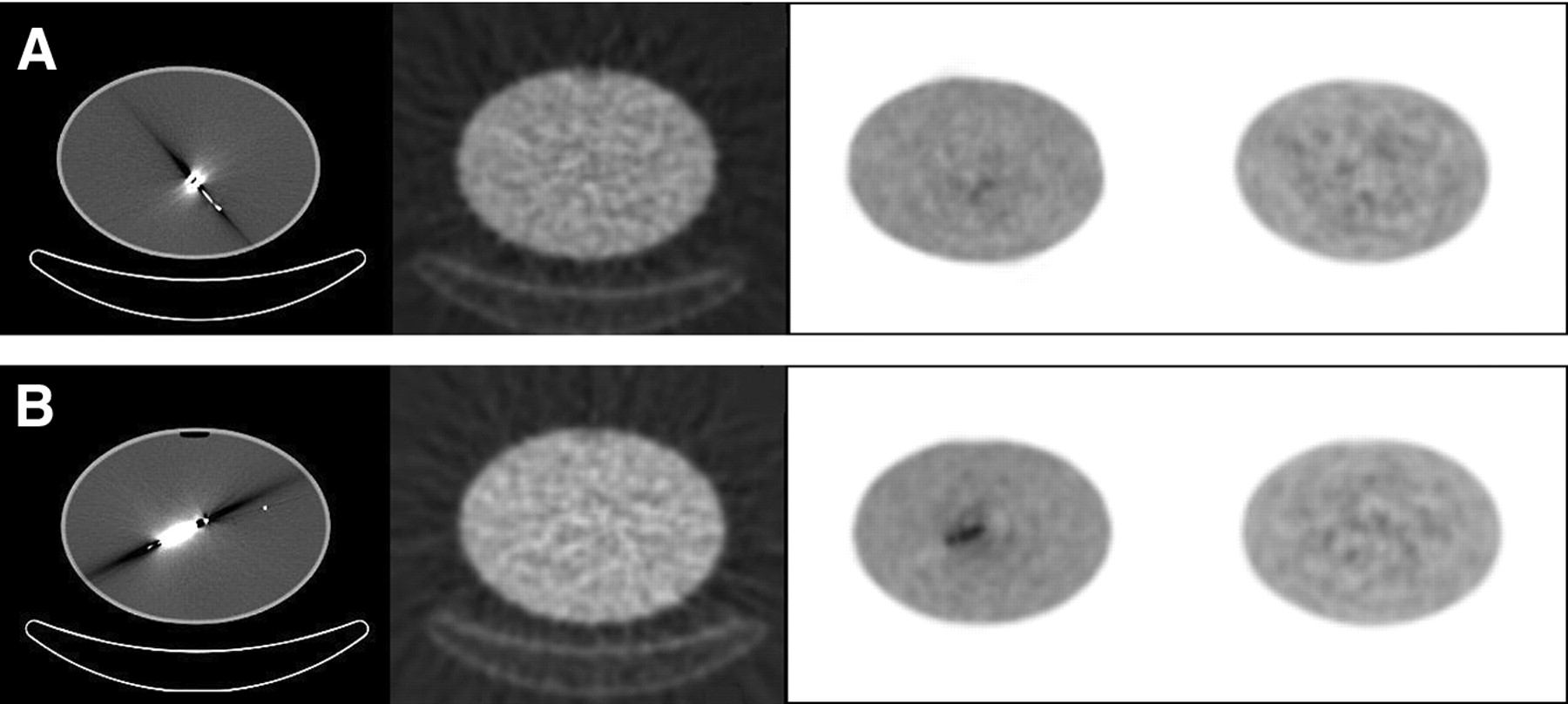
Artifacts in phantom images of pacemaker leads (A) or ICD leads in uniform activity background (B). From left to right: CT image, transmission image, PET image (Biograph) using CT-AC, and PET image (ECAT HR+) using transmission source attenuation correction.
The PET/CT images (using CT-AC) did exhibit metal-related artifact, as regions of apparent increased 18F-FDG uptake were identified at the locations of the lead electrodes. In both phantom studies, images not corrected for attenuation did not exhibit increased uptake, indicating that the features were artifactual. As shown in the phantom images, ICD lead electrodes did cause rather intense artifacts. In fact, regions of apparent reduced uptake also could be seen, corresponding to the hypointense streaks in the CT images. The pacemaker lead electrodes, on the other hand, caused much smaller artifacts that were barely noticeable relative to the image noise level. The observed artifact-related increases in 18F-FDG concentration in PET/CT images were measured to be 65% and 9% for the ICD leads and pacing leads, respectively.
The PET images (using transmission source attenuation correction) did not exhibit any visible metal-related artifact compared with the noise level of the images. Region-of-interest measurements at the known electrode locations were within 3% of mean background level, whereas the SD of the background region was 8%.
Patient Studies
Artifact-related observations and measurements are listed in Table 1 for the 15 patient studies. Patient myocardial 18F-FDG images and polar maps from both the PET/CT and PET scanners were compared to ascertain whether artifact was noticeable. The actual locations of the implanted leads were determined from the CT images, and this information aided artifact assessment. In the CT images (Fig. 3), intense artifacts were observed for both pacemaker lead electrodes and ICD lead electrodes. The degree of artifact in CT images was greatest from ICD shock coils, extending across multiple image slices covering 30–50 mm, compared with 5–10 mm for pacing electrodes.
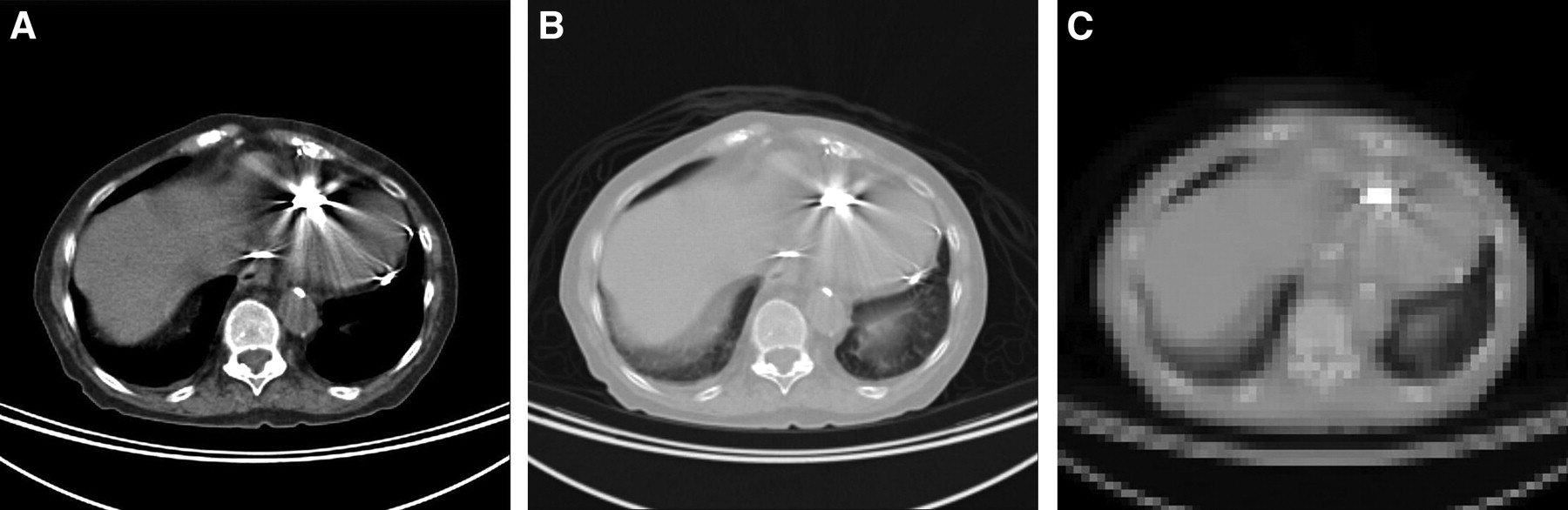
CT slice images correspond to topogram image in Figure 1, illustrating relative intensities of artifacts from ICD lead and pacing leads. (A) CT image with body window. (B) CT image with lung window. (C) Filtered and down-sampled image used for PET attenuation correction.
Observations Relating to Metallic Artifact in 15 Patient Studies
Pacing leads (total of 13 leads in 10 patients) were found to cause noticeable artifact in the CT images. However, no visible artifact arising from CT-AC was observed in the corresponding PET images.
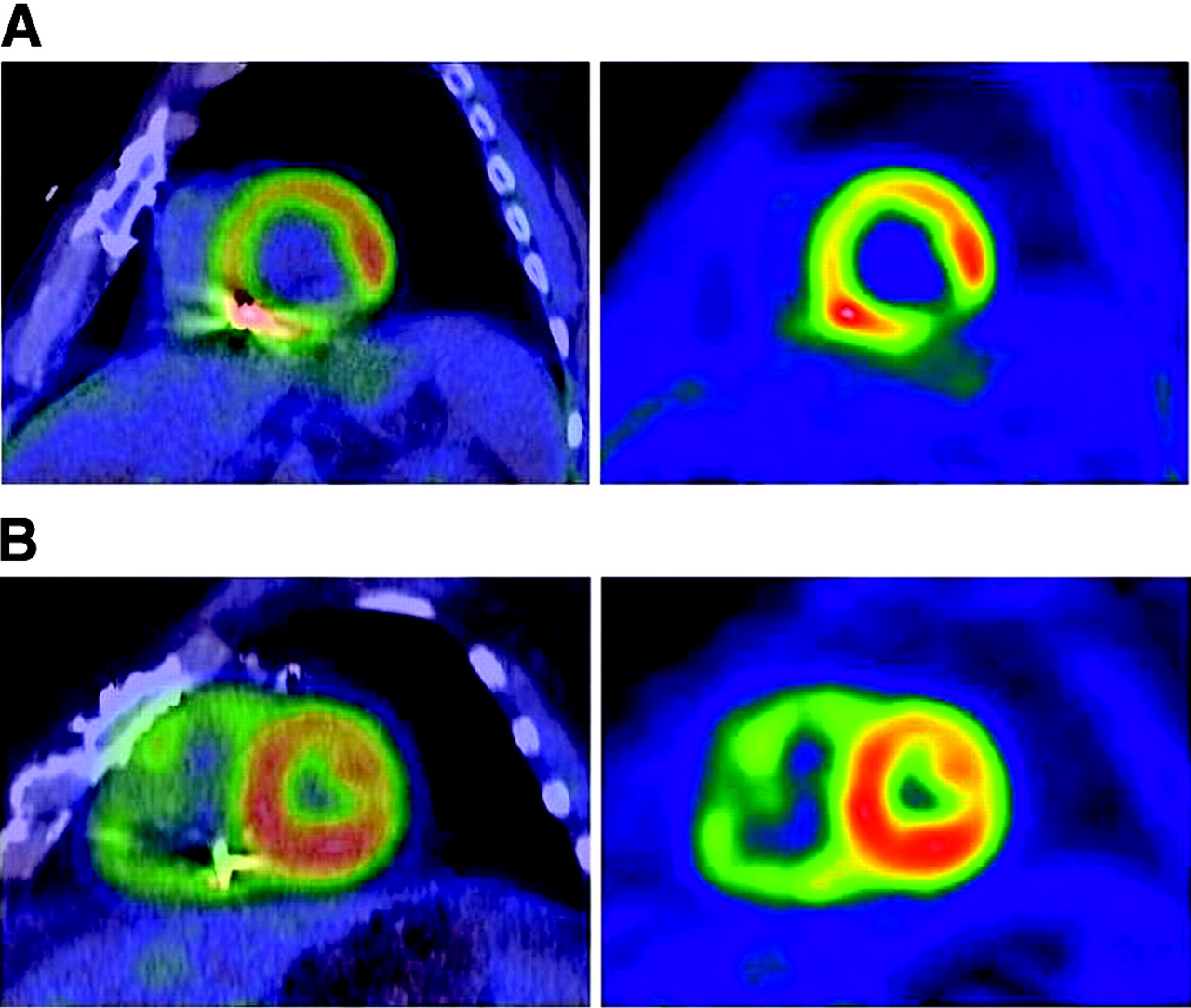
For the ICD leads (10 patients), significant artifact arising from CT-AC was observed on PET/CT images in 5 cases (50%), whereas no significant artifact was observed in the other 5 cases (50%). The artifact is clearly identifiable in surface rendered images of the left ventricle, as illustrated in Figure 4. The artifacts were all noted in the inferoseptal region of the left ventricle, as ICD shock coils typically are placed in the right ventricle near that region. The magnitude of the CT-AC–related artifact was measured from the circumferential profiles of the polar maps, relative to adjacent regions (Fig. 5). In the 5 PET/CT studies with artifact, the apparent 18F-FDG uptake at the lead location was 44%–81% greater than that of the surrounding regions. The corresponding PET images from the HR+ scanner also exhibited an increase in uptake at the lead locations, but to a much smaller degree, ranging from 11% to 28%. The increased uptake in the PET images was not related to attenuation correction, as there was no evidence of the ICD leads in the transmission images. Compared with the HR+ PET images, the metal-related artifact in the Biograph PET/CT images resulted in a mean increase in apparent 18F-FDG uptake of 30%.

Three-dimensional renderings of segmented left ventricle, with color scale indicating relative 18F-FDG uptake. Metal artifact related to implanted ICD lead near inferoseptal wall is easily seen by comparing PET/CT data (A) with PET data (B).
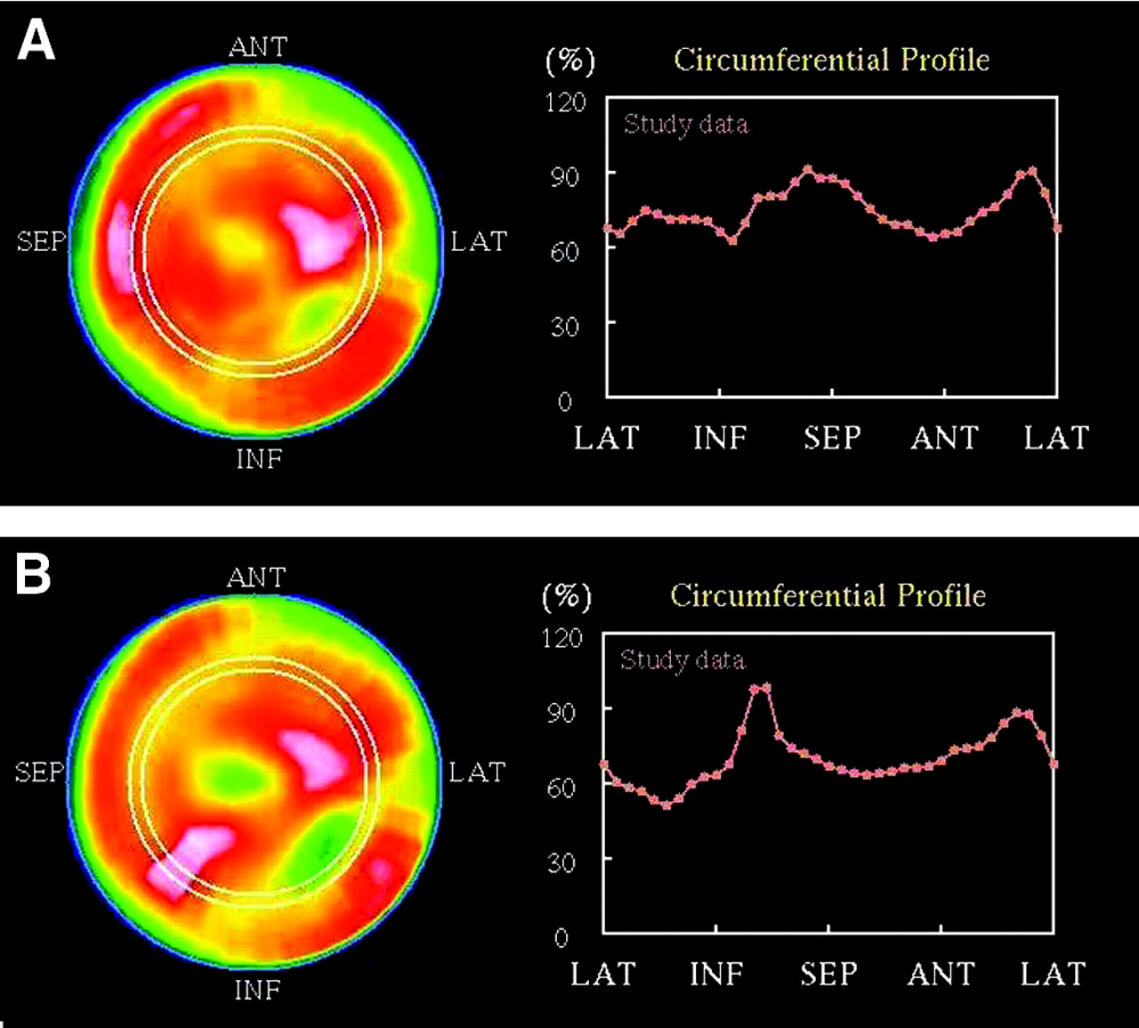
PET (A) and PET/CT (B) polar maps and circumferential profiles illustrate PET/CT metallic artifact from ICD lead. ANT = anterior; SEP = septal; LAT = lateral; INF = inferior.
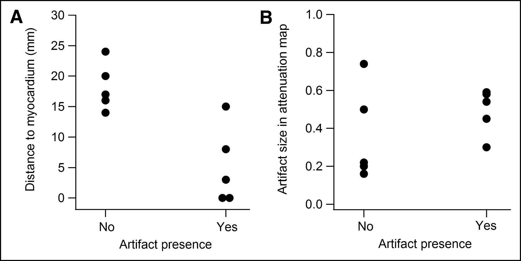
Fused short-axis images (Fig. 6) demonstrated variation in the proximity of the ICD shock coil to the left ventricle. Measurements of the distance between the shock coil and the left ventricular wall were correlated with the presence or absence of metal-related artifact (Fig. 7A). However, no relationship to the magnitude of the CT artifact was observed (Fig. 7B).

Fused PET/CT and PET images (short-axis views) from 2 studies show variation in ICD lead placement. Distance from shock coil to left ventricle is 0 mm in top images (A) and 20 mm in bottom images (B). Note different impact on left ventricular regional uptake depending on shock coil proximity.

Plots of measured distance from ICD shock coils to left ventricle (A) and magnitude of corresponding artifact in CT-AC attenuation maps (B), with respect to presence or absence of metal-related artifact in PET/CT images.
DISCUSSION
Artifacts in PET/CT due to metallic implants arise mainly from the discrepancy between the relative attenuation coefficients at high and low energies and the assumption of the CT-AC scaling algorithm that high-density regions in CT images arise solely from bone. Since most metals have a higher atomic number than calcium (the main absorptive element in bone), they have significantly higher photoelectric cross sections at x-ray energies. At 511 keV, γ-ray interactions are dominated by Compton scattering, and metals have similar absorption cross sections per unit mass as other materials. Thus, the relative absorption from low to high energy is much higher for metals than bone, causing overcorrection in CT-AC and corresponding “hot” artifacts in PET/CT images. Dedicated PET scanners with transmission sources avoid such metal artifact, since the transmission γ-ray energies are equal to or similar to 511 keV.
Because photoelectric absorption is strongly dependent on atomic number, the elemental composition of metallic implants is an important consideration. Both pacemaker leads and ICD leads contain central conductor wires that connect the electrodes to the pacemaker or ICD device. The conductor wires consist of MP35N (an alloy of Ni, Co, Cr, and Mo) or MP35N with a silver core for high-current applications (mainly defibrillation). Pacing leads typically have an electrode pair at the tip comprised of a tip electrode and a ring (or band) electrode, both of which are used for sensing intracardiac electrical activity and administering low-voltage pacing stimuli. These pacing electrodes are commonly made of platinum-iridium (Pt alloyed with 10%–20% Ir). ICD leads also have similar pacing electrodes at the tip but additionally have 1 or 2 defibrillation electrodes (“shock coils”) for delivering high-energy cardioversion pulses. The shock coils are usually 5- to 10-cm long and are most commonly located in the right ventricle and the superior vena cava. The majority (approximately 70%) of shock coils are made of platinum or platinum-iridium, whereas the remaining (approximately 30%) are made of tantalum with platinum coating. A few older defibrillation lead models have titanium shock coils, but these are not common.
Table 2 lists attenuation coefficients for water, bone, and selected metals at 50, 80, 140, and 511 keV, calculated using the NIST XCOM program (17). Since platinum, iridium, and tantalum all have both high atomic numbers (Z = 78, 77, and 73, respectively) and high mass densities (ρ = 21.4, 22.4, and 16.7, respectively), their photoelectric absorption coefficients are among the highest of all common materials. As a result, the ratios of their absorption coefficients at x-ray energies relative to those at 511 keV are very high relative to other common metals; therefore, they are ideal for causing PET/CT artifacts. Although the physical dimensions of the electrodes and shock coils are not very large, their x-ray absorption properties are of sufficient magnitude to create substantial CT artifacts.
Calculated Linear Attenuation Coefficients (Total Minus Rayleigh Scattering) of Water, Bone, and Selected Metals
In contrast, the central conductor wires, made of materials with lower atomic numbers and mass densities, have smaller attenuation coefficients. As a result, they did not cause noticeable artifacts in the PET/CT images. Our discussion on metal-related artifact therefore focuses on the electrodes and shock coils, and not the conductor wires. Other metal objects of similar size and density, such as sternal wires and surgical clips (Fig. 1), were not observed to cause PET/CT artifacts. We also infer that other small metal implants of similar atomic number and density, such as stents made of nitinol (an alloy of nickel and titanium), would not cause significant artifacts.
As noted in both the phantom images (Fig. 2) and the patient images (Fig. 3), the radioopaque platinum electrodes cause substantial CT artifacts, especially the larger-sized ICD shock coils. Although the CT artifacts are intense, the factor of greater concern is their impact on the attenuation correction of PET data. After the CT-to-PET scaling algorithm is applied, the attenuation map derived from the CT image is filtered and down-sampled from a 512 × 512 matrix to a 128 × 128 matrix. These processing steps serve to minimize the degree of artifact in the attenuation map. In the patient example in Figure 3 (right), the pacing electrode is not prominent in the attenuation map, whereas the ICD shock coil is still clearly seen. This observation is consistent with the fact that there were no noticeable PET/CT metal-related artifacts associated with pacing leads in the patient images. Only a very minor pacing lead artifact was noted in the phantom study, but it was likely due to the higher overall count density and reduced image noise as compared with the patient studies.
PET/CT artifacts relating to the ICD leads were clearly identifiable in the phantom images, but such artifacts were seen in some, but not all, patient studies. One might anticipate that the presence of metal-related PET/CT artifacts is related to the magnitude of the artifact in the CT-based attenuation maps. Due to variations in electrode design (metal composition, wire thickness, coil dimensions, and so forth), certain models of shock coils produce more intense CT artifacts than others. In addition, the magnitude of CT artifact may also be affected by the lead placement, CT acquisition parameters, patient girth, and respiratory and cardiac motion. However, no significant correlation between the magnitude of attenuation map artifact and the presence of PET/CT artifact was found (Fig. 7B).
A better explanation for the presence or absence of artifact was the proximity of the ICD shock coil to the left ventricle. The measured distances in the patient studies ranged from 0 mm (in contact) to 24 mm. Lead placement can vary from patient to patient and, in addition, misregistration due to breathing mismatch or patient motion can also contribute to variations in apparent shock coil location. Distances from the shock coil to the left ventricular wall were strongly correlated with observed PET/CT artifact (Fig. 7A). The effect of the ICD shock coil on CT-AC appears to have a range of roughly 15 mm. Assessment of myocardial uptake therefore will likely be affected if the lead is within this distance of the left ventricle.
The average magnitude of PET/CT artifact (increase in apparent local uptake compared with the PET images) was 30%. This degree of artifact is clearly noticeable and is clinically significant. Aside from creating an anomalous region of high uptake or masking a possible local defect, the artifact from the ICD shock coil can interfere with the normalization of the myocardial segments and thereby affect clinical interpretation. This affects the relative tracer uptake in the myocardial segments and would impact quantitative analysis software relying on normal databases. Viewing the fused PET and CT images may help a physician to identify the artifact and to compensate for it in his or her clinical interpretation. Although such attempts to “read through” the artifact may be sufficient in some cases, there may be errors in other cases. Software-based algorithms that accurately correct for the artifact during image reconstruction would likely provide better results.
An interesting observation was that in many cases with metal-related PET/CT artifact, there was a small increase in local uptake on the PET images, which mirrored the spatial location and extent of the ICD shock coil (Fig. 4). This effect was not an artifact of transmission source attenuation correction, since the lead was not visible in the transmission images and since a similar effect was not observed in the phantom studies. The increased local uptake appeared to be real and related to the presence of the ICD lead. One possible explanation is that this increased uptake may correspond to local inflammation of tissue near the shock coil, although no conclusion can be made at this point without further investigation.
The clinical significance of metal-related artifacts from implanted cardiac leads depends on the prevalence of such devices in the population examined. Approximately 20% of patients at our institution undergoing cardiac PET scans (82Rb perfusion or 18F-FDG viability studies) have either ICDs or pacemakers implanted. Although pacing leads do not appear to cause significant artifact, a considerable number of patients with ICD leads are affected.
With the increasing prevalence of ICDs in clinical use and the growing market dominance of PET/CT scanners, the number of cardiac PET studies affected by ICD-related artifacts is expected to increase. Therefore, automatic software-based correction for such artifacts in cardiac PET/CT is highly desirable. Such correction software would allow the attenuation values based on the measured CT Hounsfield units in the vicinity of the metallic implants to be replaced by those that better approximate the actual attenuation coefficients at 511 keV. Preliminary research in correction of artifacts from oral contrast and metal implants in oncology PET/CT using automated segmentation has shown promise (18), and a similar approach may benefit cardiac PET/CT as well. Since neither automatic nor manual corrections are currently supported on commercial PET/CT scanners, artifact from implanted ICD leads is a potentially significant clinical issue. Until correction software becomes available, fused images of cardiac PET patients with implanted ICD leads must be carefully inspected to determine whether artifact is present and whether the images are nondiagnostic. Or, these patients should be excluded from PET/CT systems not supporting transmission source attenuation correction.
CONCLUSION
Although pacemaker leads and ICD leads both cause noticeable artifacts in CT images, only ICD leads caused significant artifacts in cardiac PET images with CT-AC. These artifacts arising from the highly radioopaque shock coils were present in half of the patient studies with ICDs and caused an increase in apparent uptake, on average, 30% higher than surrounding regions. The presence or absence of the artifacts depended mainly on the proximity of the ICD shock coil to the wall of the left ventricle.
Acknowledgments
The authors thank Diane Muff (St. Jude Medical, Inc.) and Dr. Wael Jaber and Dr. Walid Saliba (both of Cleveland Clinic) for providing ICD and pacing leads for our phantom studies. We also are grateful to Diane Muff, Jim Barcel (Enpath Medical, Inc.), and John Helland (St. Jude Medical, Inc.) for technical discussions on design and material composition of ICD and pacemaker leads. Finally, we thank Tami Kaczur (Cleveland Clinic) for patient data acquisition, Curtis Howe and Kevin Lohmann (CPS Innovations) for their assistance in acquiring and processing list mode PET/CT data, and Jim Hamill (CPS Innovations) and Eoin Carney (University of Tennessee) for helpful discussions on CT-AC artifact reduction algorithms.
Footnotes
Received Aug. 17, 2004; revision accepted Sep. 27, 2004.
For correspondence or reprints contact: Frank P. DiFilippo, PhD, Department of Molecular and Functional Imaging/Gb3, Cleveland Clinic Foundation, 9500 Euclid Ave., Cleveland, OH 44195.
E-mail address: difilif{at}ccf.org
REFERENCES
In this issue


Jump to section
Related Articles
Cited By...
- Joint SNMMI-ASNC Expert Consensus Document on the Role of 18F-FDG PET/CT in Cardiac Sarcoid Detection and Therapy Monitoring
- Characterization of 18F-Fluorodeoxyglucose Uptake Pattern in Noninfected Prosthetic Heart Valves
- Advanced Imaging of Cardiac Sarcoidosis
- Quantitative Assessment of Artifacts on Cardiac Magnetic Resonance Imaging of Patients With Pacemakers and Implantable Cardioverter-Defibrillators
- Noninvasive Characterization of Myocardial Molecular Interventions by Integrated Positron Emission Tomography and Computed Tomography