


Abstract
Accurate anatomic localization of functional abnormalities seen with PET is known to be problematic. Even though nonspecific tracers such as 18F-FDG visualize certain normal anatomic structures, the spatial resolution is generally inadequate for localization of pathology. Combining PET with a high-resolution anatomic imaging modality such as CT can resolve the localization issue, as long as the images from the two modalities are accurately coregistered. However, software-based registration techniques have difficulty accounting for differences in patient positioning and involuntary movement of internal organs, often necessitating labor-intensive nonlinear mapping that may not converge to a satisfactory result. Acquiring both CT and PET images in the same scanner obviates the need for software registration and routinely provides accurately aligned images of anatomy and function in a single scan. Discussion: A CT scanner positioned in tandem with a PET scanner and with a common patient couch and operating console has recently been explored as a solution to anatomic and functional image registration. Axial translation of the couch between the two modalities enables both CT and PET data to be acquired during a single imaging session. In addition, the CT images can be used to generate noiseless attenuation correction factors for the PET emission data. By minimizing patient movement between the CT and PET scans, and after accounting for the axial separation of the two modalities, accurately registered anatomic and functional images can be obtained. Since the introduction of the first PET/CT prototype a little over 5 years ago, several thousand cancer patients have been scanned on combined PET/CT devices. In the past 3 years, a number of commercial designs have become available featuring multidetector spiral CT scanners and high-performance PET devices. Initial experience has demonstrated an increased level of accuracy and confidence in the interpretation of the combined study compared with separate readings, particularly in the ability to distinguish pathology from normal physiologic uptake and to precisely localize abnormal foci. Conclusion: Combined PET/CT scanners represent an important evolution in technology that is helping to bring molecular imaging to the forefront in cancer diagnosis, staging, and therapy monitoring.
Accurate anatomic localization of functional abnormalities seen on PET scans is well known to be challenging because of the lack of detailed, high-resolution anatomy. For tracers such as 18F-FDG, limited anatomic information is available from nonspecific uptake in muscles, brain, heart, liver, colon, and other organs, whereas excretion through the urinary system enables visualization of the renal collecting systems and bladder. Localization relative to such low-resolution anatomic landmarks may nevertheless help with interpretation even though a detailed anatomic framework such as that provided by CT would be an evident improvement.
Traditionally, imaging modalities such as CT and PET have been applied sequentially in the diagnosis and staging of disease and in monitoring the effects of therapy. Indeed, in many cases anatomic imaging is used exclusively, although functional imaging with PET is fulfilling an increasingly important role in the staging and therapy monitoring processes, particularly when the CT scan is equivocal (1). Visual fusion of the anatomic and functional image sets has often been considered sufficient to extract additional information, particularly with the perception that only a small fraction of PET studies benefits from access to corresponding CT scans. In cases in which more accurate localization is required, software fusion can be used to align the two sets of images. Sophisticated algorithms have been developed using affine and deformable transformations to align disparate image sets from different modalities. Outside the brain, however, software fusion is difficult and often unsuccessful because of the many degrees of freedom accessible to the human body when imaged by two different modalities on two different occasions. At best, the alignment process is labor intensive and far from routine at most medical centers.
This situation changed dramatically with the recent introduction of the combined PET/CT scanner, an approach that solves the fusion problem through hardware rather than software. Such a device provides a medical imaging department with the capability to acquire accurately aligned anatomic and functional images for a patient from a single scanning session. Additionally, since the patient remains positioned on the same bed for both imaging modalities, temporal and spatial differences between the two sets of images are minimized. Spatial differences include not only overall patient positioning and movement but also the involuntary and uncontrollable motion of internal organs. Thus, by eliminating the need for labor-intensive software fusion, registered anatomy and function can be acquired routinely for every patient, with the images available for viewing while the patient is still in the scanner.
Despite some impressive progress in the development of software registration algorithms (2), there are several reasons to prefer the hardware approach to combining CT and PET imaging, as summarized in Table 1. The technology, more than just the fusion of two accepted modalities, represents an evolution in imaging instrumentation. The availability of this technology has realized aspects of combined imaging that are difficult or impossible to appreciate with separate devices, such as the use of CT for attenuation correction of PET, the convenience for both physician and patient of a single scan for both modalities, and increased confidence in study interpretation that originates from having coregistered anatomy and function available immediately after the scan. There are cases where a suspicious finding on one modality invites a closer examination of the other modality, a retrospective image review that can take place immediately after the PET/CT scan has concluded.
Comparison of Software and Hardware Image Fusion
Since the introduction of the first PET/CT prototype in 1998 (3), a number of different designs have been offered by the major vendors of medical imaging equipment. All designs comprise a CT scanner placed in tandem with a PET scanner with little or no mechanical integration of the two modalities. A common patient couch, however, enables combined PET/CT imaging to be performed with an axial translation of the bed. Since patient movement is minimal and the CT and PET scans are acquired within a short time span, accurate alignment of the two image sets is automatic. Even though combined PET/CT scanners have been in clinical operation for less than 3 years, they have already evolved through several generations with performance enhancements in both CT and PET components. The principal features of current PET/CT scanners will be reviewed, and the strengths and weaknesses of the different aspects emphasized. Particular consideration will be given to a discussion of CT-based attenuation correction. From the rapid progress seen in the past 3 years, it is evident that PET/CT technology will continue to evolve in the future. Some potential directions for the PET/CT scanners of tomorrow will be discussed.
FROM CONCEPT TO PRACTICE
Developing the Concept
The PET/CT scanner, by combining two established modalities such as CT and PET, is an evolution in imaging technology, integrating two existing technologies that have historically progressed along separate but parallel paths. The two modalities are complementary, with CT images lacking the functional specificity of PET and PET images lacking the anatomic detail seen on CT. Since its inception in the early 1970s, CT has developed into a high-throughput, rapid, reliable, and widely used modality yielding good-quality, high-resolution images of x-ray attenuation. Despite the introduction of MRI into the clinic in the early 1980s, CT has remained a major imaging modality with steadily improving performance. In many applications, such as radiation therapy planning, CT is still the anatomic imaging modality of choice. PET, on the other hand, was primarily a neuroscience research tool until 1999 when reimbursement was approved for whole-body 18F-FDG scanning for certain cancers. Compared with CT, 18F-FDG PET scans have lower spatial resolution and higher levels of noise and require significantly longer imaging times, resulting in low patient throughput.
From PET to PET/CT Prototype
The first PET/CT prototype (3) was introduced into the clinical arena in 1998. The approach taken was to modify an existing spiral CT scanner, a SOMATOM AR.SP (Siemens Medical Solutions), to incorporate PET imaging capability. The PET detectors were mounted on the rear of the CT rotating support, as shown schematically in Figure 1. The PET components consisted of two arrays of bismuth germanate (BGO) blocks covering an axial field of 16 cm with 24 partial rings of detectors, as in the ECAT ART scanner (CPS Innovations). The ART design had no septa, and data acquisition was fully in 3-dimensional (3D) mode (4). The prototype, therefore, comprised a single integrated assembly with both CT and PET imaging capability, rotating together at 30 rpm. Axial translation of the couch then allowed the patient to be moved automatically from the CT to the PET imaging fields 60 cm apart. Since the systems were intrinsically aligned on the same mechanical support, the corresponding images were accurately registered. The acquisition, reconstruction, and operating systems were not integrated; different consoles controlled the operation of the CT and the PET. The CT images were transferred to the PET console by Ethernet to be used for CT-based attenuation correction and fused image viewing. The goal of this design (5,6) was to acquire clinical-quality CT and PET scans for every patient, even though both devices were somewhat limited in performance. The maximum co-scan range for CT and PET was 100 cm, with a scan duration of around 45 min, due mainly to PET acquisition time. More than 300 cancer patients were scanned on the prototype from 1998 to 2001, and the studies suggested that, in many cases, having both anatomic and functional images routinely for all patients enhanced the potential of both modalities (7–10).
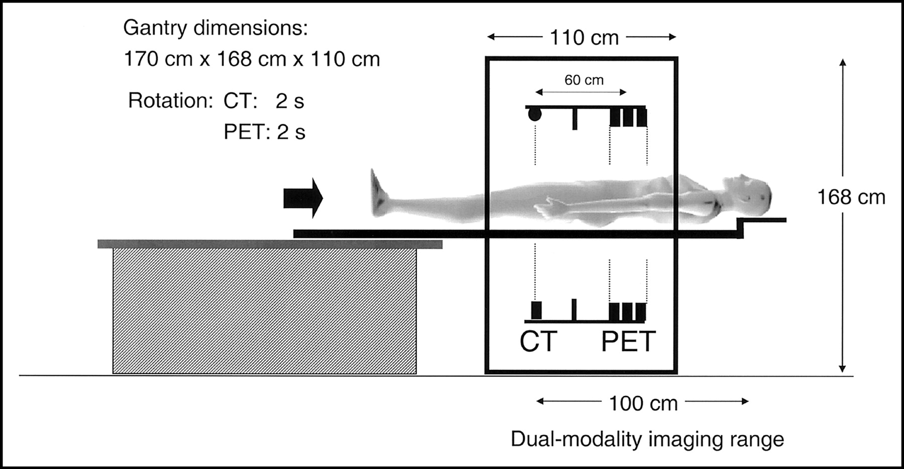
Schematic of original PET/CT prototype developed by Beyer et al. Axial separation of two imaging fields is 60 cm.
Beyond the Prototype
Clinical results from the prototype stimulated the development of PET/CT designs by major vendors of medical imaging equipment, who were encouraged by demands from radiologists and nuclear medicine physicians. One such design from CPS Innovations is shown schematically in Figure 2, incorporating high-performance CT and PET and a new design for the patient couch. The rotating partial rings of PET detectors are replaced with fixed complete rings, and the CT scanner is upgraded to a dual-slice SOMATOM EMOTION (Siemens Medical Solutions). The PET scanner could be either a BGO-based ECAT HR+ or a lutetium oxyorthosilicate (LSO)-based ECAT ACCEL (CPS Innovations). Both the BGO and LSO versions are without septa and operate entirely in 3D acquisition mode. Also, since no PET transmission sources are incorporated into the design, CT-based attenuation correction is standard on these systems. Of note in this design is the minimal level of actual hardware integration compared with the prototype shown in Figure 1. The two scanners are simply placed in tandem within the gantry housing. The gantry is 188 cm high and 228 cm in width. The overall length is 158 cm, although with front and rear contouring, the effective tunnel length is only 110 cm. The axial separation of the centers of the CT and PET fields of view is about 80 cm. Also of interest is the new patient handling system, or couch, that eliminates a relative vertical deflection of the pallet as it moves through the tunnel. Instead of the usual design, in which the pallet moves over a fixed support so that the cantilever point changes (Fig. 1), in this design the pallet is attached to a pedestal at a fixed point and the entire assembly moves into the scanner as a single unit on floor-mounted rails. Thus, once the patient is installed on the couch, no further deflection occurs during the scan. The co-scan range for combined CT and PET imaging is at least 145 cm. The patient port diameter is 70 cm throughout the length of the tunnel, an important feature when scanning patients for radiation therapy. The larger port diameter allows patients to be positioned exactly as they would be for radiation treatment, particularly if high-precision lasers are installed in the PET/CT room. Patients receiving radiation treatment for breast cancer are frequently positioned with one or both arms raised, a position that can be a challenge even for a 70-cm port.
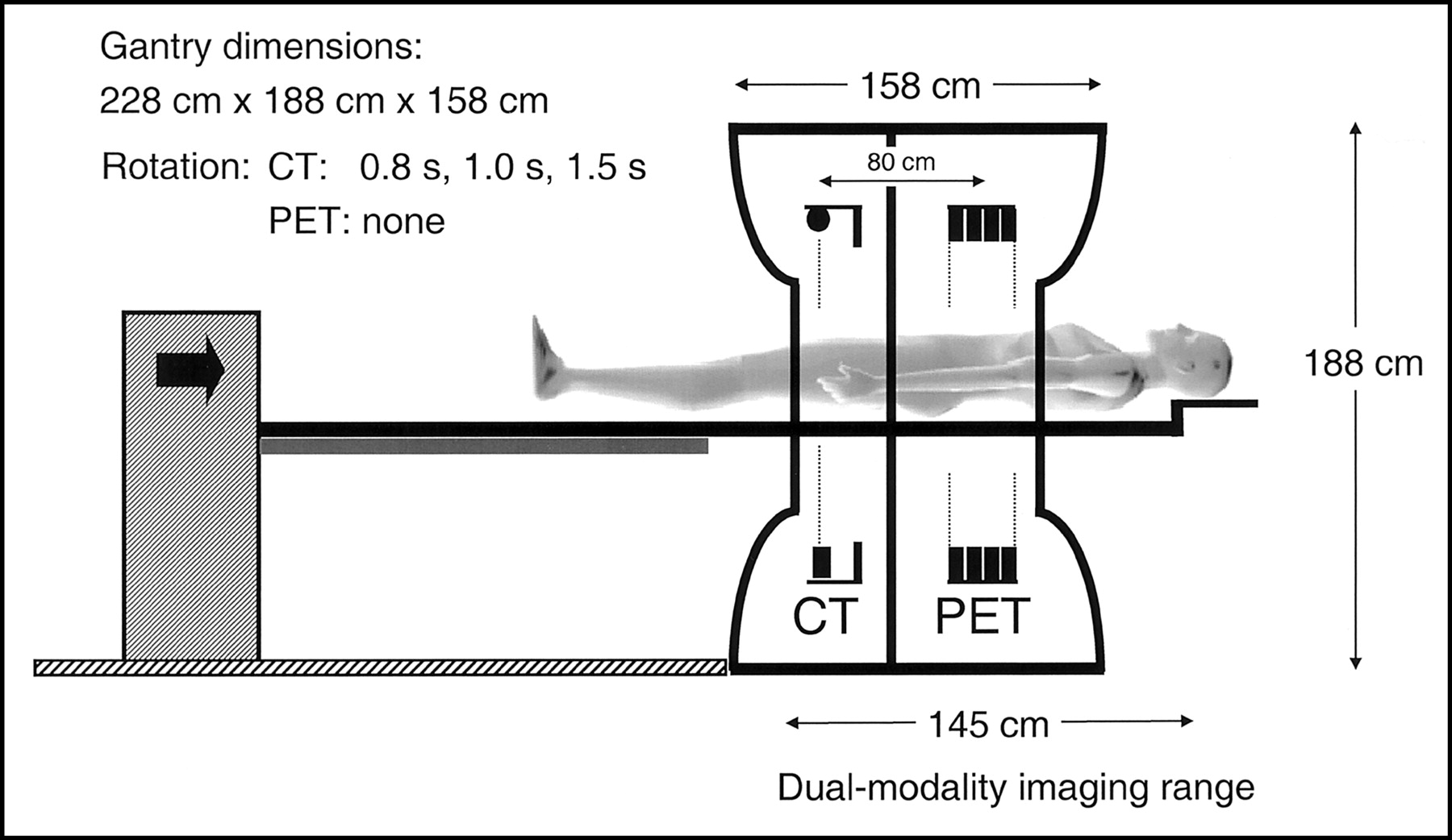
Schematic of PET/CT developed by CPS Innovations. Axial separation of two imaging fields is 80 cm. The co-scan range for acquiring both PET and CT has maximum of 145 cm.
A much closer integration of control software is achieved compared with the prototype, even though at this stage acquisition and reconstruction are still performed on separate hardware. With a single operating console, the computers involved in the acquisition and reconstruction processes are transparent to the user. Fused image analysis and display software is available on a separate workstation for review of the studies. The software offers a wider range of options for CT, PET, and fused image manipulation than was available with the prototype, including measurement and analysis tools traditionally used by radiologists and nuclear medicine physicians when reading CT and PET studies, respectively.
PET/CT TODAY
The design shown schematically in Figure 2 is typical of PET/CT scanners of today. Differences in the performance of CT and PET components, design of the patient couch, and operating system and software distinguish the various vendors.
Current PET/CT Designs
The first scanner to appear commercially with the capability to image anatomy and function was the Hawkeye (GE Medical Systems), shown in Figure 3A. A low-powered x-ray tube and detectors are mounted on a Millennium VG dual-headed γ-camera (11). The low-resolution anatomic images are acquired at 2.6 rpm, with a single slice being imaged in about 14 s. Clinical studies with this device (12,13) have helped to re-emphasize the importance of imaging anatomy and function together in the same scanner. The design shown in Figure 2 and described in the previous section obtained FDA clearance in October 2000 and is currently marketed by Siemens Medical Solutions as the biograph and by CTI Inc. as the Reveal (Fig. 3B). The first dedicated PET/CT design from GE Medical Systems, the Discovery LS, was announced at the Radiological Society of North America (RSNA) meeting in December 2000. The design (Fig. 3C) features a Lightspeed Plus HiLite multidetector CT (MDCT) scanner with an ADVANCE NXi BGO-based PET scanner. The ADVANCE scanner in the PET/CT is essentially unchanged from the stand-alone version, incorporating both retractable septa and optional standard PET transmission sources. The patient port is 70 cm for the CT, tapering to 60 cm for the PET, somewhat limiting the application of the device for radiation therapy treatment planning, for which a larger patient port is preferred.
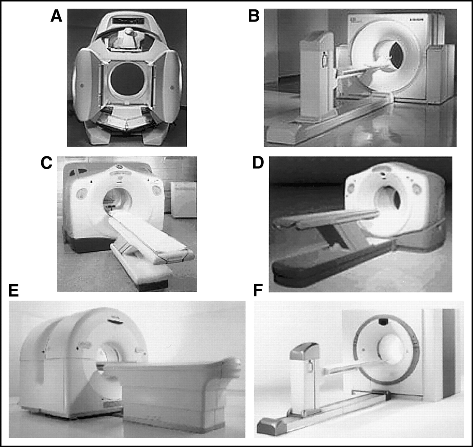
Current commercial PET/CT scanners from 4 major vendors of PET imaging equipment: (A) Hawkeye (GE Medical Systems); (B) biograph (Siemens Medical Solutions) or Reveal (CTI, Inc.); (C) Discovery LS (GE Medical Systems); (D) Discovery ST (GE Medical Systems); (E) Gemini (Philips Medical); (F) biograph Sensation 16 (Siemens Medical Solutions) or Reveal XVI (CTI, Inc.).
A rather different approach to a PET/CT design is the Gemini, manufactured and marketed by Philips Medical. This is a more open configuration than others, with the CT and PET scanners separated to allow access to the space between the two devices (Fig. 3E). The Gemini comprises a Philips MX 8000D dual-slice CT scanner with a gadolinium oxyorthosilicate GSO–based ALLEGRO PET scanner. The ALLEGRO has no septa and operates entirely in 3D. The patient port diameter is 70 cm for CT, reduced to 63 cm for the PET, again somewhat limiting the application of the device for radiation therapy planning.
Recent additions to the range of PET/CT scanners were presented at the RSNA meeting in December 2002. General Electric announced the introduction of the Discovery ST, a PET/CT device with a redesigned BGO-based PET scanner that incorporates finer axial sampling, an increased number of detector rings, shorter septa, and a 70-cm patient port throughout the entire length (Fig. 3D). The CT scanner is a Lightspeed Plus HiLite MDCT. The exterior gantry dimensions of the redesigned PET scanner now match those of the Lightspeed CT (Fig. 3D). At the same meeting, Siemens Medical Solutions announced the biograph Sensation 16 (Fig. 3F), a PET/CT scanner developed by CPS Innovations that comprises a 16-slice, high-performance CT scanner with the LSO-based ACCEL PET scanner. CTI Inc. markets this device as the REVEAL XVI.
Some of the key parameters featured in the current range of PET/CT devices from different vendors are summarized in Table 2. CT scanners offer a range of different detectors and rotation speeds, with mid- to high-performance x-ray tubes. The time to scan an axial range of 100 cm varies from 13 s for a 16-slice system up to 90 s for a single-slice unit. All CT patient ports are 70 cm in diameter. PET scanner designs incorporate different scintillator material, with detector sizes in the 4–6 mm range. The axial coverage is 15–18 cm, and some designs include retractable septa between the detector rings, offering both 2D and 3D acquisition capability. These designs also offer optional PET transmission sources as an alternative to CT-based attenuation correction. While PET/CT design parameters may vary considerably (Table 2), all devices produce essentially good-quality whole-body PET/CT scans in less than 30 min.
CT and PET Parameters in Current PET/CT Designs
To illustrate the performance of one such device, a PET/CT study acquired on a 16-slice LSO PET/CT is shown in Figure 4. The patient is a 66-y-old man with a history of both head-and-neck and lung cancer. Uptake in the lung malignancy (arrowhead) is clearly seen on the PET (Fig. 4A) and fused coronal images (Fig. 4C). The CT was acquired with breath hold at end expiration and shows clear delineation of the right lung base and upper pole of the liver. Suspicious uptake was also noted close to the midline, anterior and inferior to the bladder (arrows). Localization of the uptake was difficult with the PET scan alone, and a subsequent 99mTc bone scan (Fig. 4B) confirmed a bone metastasis. The fused images (Fig. 4C) clearly localized the uptake to the pubic ramus, allowing the stage of disease to be assessed from a single study.

Images of 66-y-old male patient with history of head-and-neck and lung cancer. In addition to uptake in lung malignancy, intense uptake is seen on PET scan (A) in midline, anterior and inferior to bladder. Note also presence of lung lesion (arrowhead) due to primary lung cancer. 99mTc bone scan (B) subsequently confirmed that uptake was due to metastatic bone disease. PET/CT scan (C) directly localized uptake to pubic ramus (arrowed). Scan parameters were: CT: 101 mAs, 120 kV, and 5-mm slices; PET: 13 mCi 18F-FDG, 150 min after injection, 5 min/bed, 7 bed positions.
As PET/CT technology becomes more widely available, studies are beginning to appear in the literature that document the use of PET/CT in a variety of different cancers, including lung (14–16), thyroid (17), ovarian (18), lymphoma (19), and unknown primary cancers (20), and for general oncology applications (21,22). Specific applications of PET/CT, such as those for radiation therapy planning, are also being explored (23,24).
CT-Based Attenuation Correction
While the acquisition of accurately coregistered anatomic and functional images is a major strength of the combined PET/CT scanner, an additional advantage of the hardware fusion approach is the use of CT images for attenuation correction of the PET emission data, eliminating the need for a separate, lengthy PET transmission scan. The use of the CT scan to generate PET attenuation correction factors (ACFs) not only reduces whole-body scan times by up to 40% but also provides essentially noiseless ACFs compared with those from standard PET transmission measurements, even with singles sources. The attenuation values (μ) are energy dependent. Therefore, the correction factors derived from a CT scan at a mean photon energy of 70 keV must be scaled to the PET energy of 511 keV. Since the CT attenuation value at a given energy depends on both density and relative elemental composition of the tissue, the scale factor is determined by the fractional elemental composition rather than the density, i.e., attenuation is related to electron density. Generally, a higher effective atomic number for the tissue implies a smaller scale factor because the attenuation decreases more rapidly with energy.
The behavior of the scale factor calculated from the ratio of attenuation values μ(at 511 keV)/μ(at 70 keV) as a function of CT number is shown in Figure 5. These attenuation values are for standard reference tissues (25). Even though lung tissue has a much lower density than water, it nevertheless has a very similar elemental composition and, therefore, a similar scale factor to other soft tissues, close to that of water. Adipose tissue has a slightly higher scale factor because of its composition. Compared with soft tissues, bone-related tissue is less uniform in composition, as shown in Figure 5. Bone tissues behave according to a water–bone mix with different fractional contributions from water-like and cortical bone-like tissue. Scale factors for bone are smaller than those for soft tissue, and an exact scaling procedure would account for the small differences between bone types. However, that would require a sophisticated segmentation of the different bone structures seen in a CT image. In practice, a simpler approach used in current PET/CT scanners is to transform the attenuation values above and below a given threshold with different factors (26,27). In the approach used by Kinahan et al. (26), the threshold distinguishes regions of bone from those of nonbone. Within these two categories, no further distinction is made between the various subtypes of tissue. As seen in Figure 5, while a single scaling factor is a good approximation for soft tissue, a water–bone mixing model would be more appropriate for bone tissue. However, in a typical CT image the volume of bone-related pixels is small compared with the volume of soft tissue, and the use of a single scaling factor will not introduce appreciable error. This appears also to hold for the pelvic region, where the volume of bone relative to soft tissue is somewhat larger. The original CT images acquired at a mean energy of about 70 keV are thus scaled on a pixel-by-pixel basis up to 511 keV. The scaled CT images are then interpolated from CT to PET spatial resolution, and the ACFs are generated by reprojection of the interpolated images.

Plot of ratio of μ(511 keV)/μ(70 keV) as function of CT Hounsfield unit (HU) for reference tissues, as given by International Commission on Radiological Protection in 1975 (25). Scaling factors used in algorithm of Kinahan et al. (26) for soft tissue (water) and bone are indicated by horizontal lines.
Serious effects potentially arise from the mismatch between the CT and PET images due to patient respiration. This mismatch is at a maximum when the clinical CT is acquired with breath hold at full inspiration (maximum expansion of the thorax) while the PET is acquired with the patient breathing normally. Alternative protocols that incorporate either breath hold at partial inspiration for the CT acquisition or allow shallow breathing throughout both the CT and PET scans are also being explored (28–30). The anatomic regions most affected by breathing artifacts include the diaphragm, base of the lung, and upper pole of the liver. The use of multislice CT and a 25-s scan time may help to eliminate such artifacts by allowing the CT scan to be acquired with breath hold at end expiration (as for the patient in Fig. 4). A recent publication (31) noted that, in 300 patients with proven liver lesions, approximately 2% appeared to have the lesion localized in the lung due to respiratory motion. Care must be exercised when diagnosing patients with disease in the region of the base of lung, diaphragm, and upper pole of the liver if breathing is allowed during the CT scan.
Iodinated contrast is used in CT to enhance attenuation values in the vessels (intravenous administration) and gastrointestinal tract (oral administration). Contrast-enhanced pixels that are incorrectly scaled to 511 keV can potentially generate focal artifacts in the PET image. This would be an undesirable outcome, particularly for tumor imaging. Of course, avoiding the administration of contrast would also eliminate the problem. However, standard-of-care CT scanning generally dictates the use of either intravenous or oral contrast or both, as in scanning of the abdominal and pelvic regions. One obvious way to avoid such problems is to perform two CT scans, a clinical CT with appropriate contrast administration and a low-dose, noncontrast CT for attenuation correction and coregistration. The two scans could even be acquired with different breathing protocols. This two-scan approach, however, would further increase the radiation exposure to the patient. Recent results (32) have shown that the presence of intravenous contrast at normal concentrations actually has little effect on the CT-based ACFs.
Unfortunately, this is not the case for oral contrast, with which the larger intestinal volumes and wide range of concentrations can lead to overcorrection of the PET data. However, Carney et al. (33) have shown that a modification can be made to the original algorithm of Kinahan et al. (26) to separate contrast-enhanced CT pixels from those of bone, as shown in Figure 6. Pixel enhancement from contrast is around 170 HU at ingestion through the stomach, increasing to about 700 HU in the lower gastrointestinal tract as water is absorbed from the contrast solution (Fig. 6A). Starting with a contrast-enhanced CT scan (Fig. 6A), cortical bone pixels are identified with a threshold >1,500 HU, and a region-growing algorithm is used to identify all contiguous pixels with bone content. The skeleton can then be extracted from the CT images (Fig. 6B). Contrast-enhanced pixels are identified by applying a simple threshold at, for example, 150 HU (Fig. 6C), well above any soft-tissue value (Fig. 5). Since the presence of iodinated contrast has a negligible effect (<2%) on photon attenuation at 511 keV, the CT image pixels identified as oral contrast can be set to a tissue-equivalent value, thus ensuring accurate ACFs for the PET data. Since the presence of contrast material has a negligible effect at 511 keV, the spatial redistribution of the contrast material between the CT and PET scans does not create a problem. The aim of the modified algorithm is to remove the effect of the contrast from the CT images and avoid incorrect scaling of contrast-enhanced regions. The modified algorithm can, to a considerable extent, also reduce artifacts due to catheters and metallic objects in the patient (34).

Use of oral contrast requires modification of CT-based attenuation correction algorithm. (A) CT pixel enhancement with oral contrast solution increases from approximately 170 HU in stomach (arrowhead) after ingestion to >700 HU toward end of GI tract (arrow). Modified algorithm applies region-growing technique to contrast-enhanced CT images (A) to extract skeleton (B). Contrast-enhanced pixels (C) can then be identified by simple threshold at 150 HU, since after removal of skeleton, the only pixels with values above 150 HU will be those with contrast enhancement.
While respiratory motion and the presence of intravenous and oral contrast can generate artifacts in the PET images through CT-based attenuation correction, the CT images provide clues to potential problems. Motion artifacts seen on CT will correlate with regions of artifactually increased uptake on the PET images, and a region or regions of concentrated contrast material seen on CT may also correlate with focal uptake on PET. Such indications from the CT scan can be used to ensure a proper interpretation of the attenuation-corrected PET images. Finally, the noncorrected PET images can also be compared with the attenuation corrected images to ensure appropriate identification of artifacts due to the ACFs. Thus, even though the potential to generate artifacts exists through specific biases in CT-based attenuation correction, the considerable benefits of rapidly acquired, noiseless ACFs clearly outweigh any such disadvantages.
PET/CT TOMORROW
Recent advances in instrumentation for PET and PET/CT are profoundly changing the practice of clinical PET. These advances will continue in the future with new designs, faster electronics, increased computing power and maybe new scintillators with better physical characteristics for PET than even LSO. In the shorter term, a configuration based on rotating LSO panel detectors has recently been proposed (35) that may form the basis for a new, high-performance PET scanner.
LSO Panel Detectors
The design of the LSO panel detector shown in Figure 7 is based on a somewhat different approach to the successful BGO block detector used for almost two decades for PET (36). While a similar block structure is used in the quadrant-sharing approach (37), the photomultipliers are larger, 5-cm tubes that are bonded to the scintillator as shown in Figure 7, with the edges of the tubes positioned over the centers of the 5 × 5 cm blocks of LSO (Fig. 7A). The increased light output from LSO allows the block to be cut into 12 × 12 small crystals and still maintain the ability to separate the detector elements. The concept that has been presented (35) is to mount 3, 4, or 5 of these panel detectors in a hexagonal configuration and rotate the assembly at 30 rpm to acquire a full dataset for 3D reconstruction. One of the completed panels with 10 × 7 blocks is shown in Figure 7B. The physical dimensions are 52 × 36 cm, with the longer side mounted axially in the gantry. The completed scanner design with the covers in place is shown in Figure 7C. The axial coverage for imaging is extended compared with current PET scanners (Fig. 7D). With the large axial coverage, only one or two bed positions will be required for whole-body coverage, offering short imaging times for such studies.
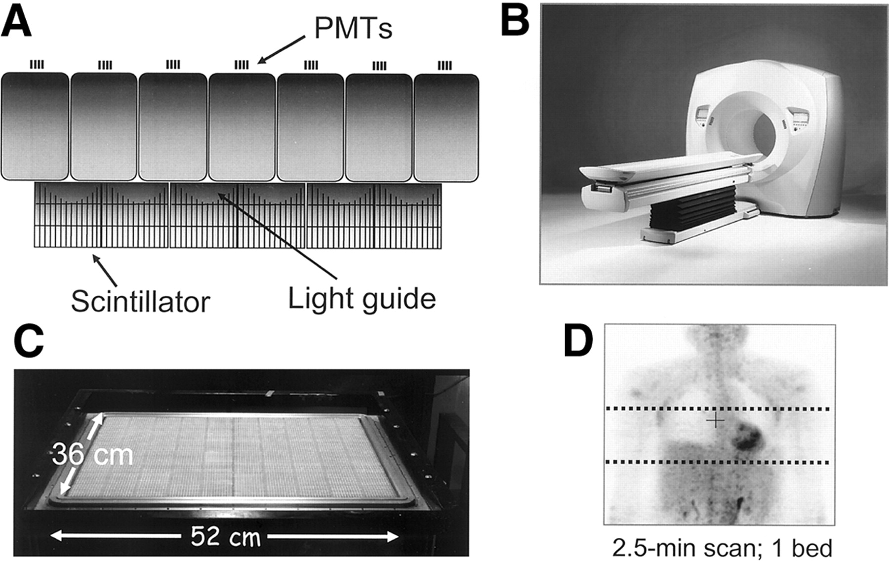
(A and B) LSO panel technology based on quadrant-sharing approach using large phototubes. (C) PET scanner based on LSO panel technology; (D) coronal section of patient scanned with single bed position. Dotted lines indicate axial extent of single bed position for current multiring scanner with 15-cm field-of-view.
Designs for the Future
Combined PET/CT scanners have been in production for less than 3 years, and the technology is undergoing rapid evolution. For PET components, the introduction of new scanner designs, scintillator materials, detector concepts, and electronics is transforming whole-body PET imaging. In parallel with these developments, the increasing number of detector rows and the reduction in rotation time are also transforming whole-body CT performance.
Nowhere has this evolution been more evident than in the dramatic reduction in scan duration, as illustrated in Figure 8, where the impact of faster scintillators and the introduction of the PET/CT concept can be appreciated. The lengthy imaging times of 1 h or more for a whole-body scan were characteristic of the technology of the mid-1990s, with the transmission scan for attenuation correction occupying 40% or more of the time the patient spent in the scanner. Improved scanner performance and the introduction of singles transmission sources reduced imaging times to below 1 hour for a full-ring BGO scanner. The appearance of the first clinical LSO-based PET scanner in 2000, the ECAT ACCEL, had a significant impact on scan duration, with whole-body imaging times decreasing to less than 30 min, particularly where higher levels of activity could be injected. However, the transmission scan still represented about 40% of the total scan duration. The impact of PET/CT has been to reduce transmission scan times to 60 s or even less through the use of CT-based attenuation correction as described previously. Twenty-minute scan times are now attainable with the BGO PET/CT, and scan times of 15 min or less are possible with the LSO PET/CT (38). For the future, integrating the panel-based PET scanner (Fig. 7) with high-performance MDCT is an attractive concept that offers unparalleled performance for both modalities, with the potential for 5-min imaging times or less (Fig. 8). Apart from enhancing patient comfort and minimizing the effect of patient movement, a further advantage of a short scan time is the economic constraints of PET/CT. By matching PET performance to that of CT, PET/CT throughput will more closely resemble that of CT alone, effectively eliminating the undesirable occupation of a high-throughput CT scanner during a lengthy PET scan.

Significant reduction in PET scan duration achieved over past few years reflecting impact of LSO, PET/CT, and CT-based attenuation correction. Darker part of each bar represents duration of transmission scan required for attenuation correction.
Interestingly, considering the impact PET/CT is already having in the diagnosis, staging, and therapy monitoring of malignant disease, there is also a demand for a device offering less performance for less cost. To meet this demand, an entry level or midrange PET/CT design is required, possibly in a form similar to the original prototype, with PET detectors mounted on the same rotating assembly as the CT (3). Since the performance of the PET components is the limitation on overall imaging time, institutions requiring high throughput and large patient volumes will demand the highest PET performance. A four- or eight-slice CT scanner may be adequate for most oncology applications, with the 16-slice CT extending PET/CT applications to the cardiology domain. However, the 16-slice design also potentially offers some interesting breath-hold possibilities for the CT protocol. As the current PET/CT technology becomes more widely adopted, appropriate future designs of this concept will be refined.
DISCUSSION
PET/CT technology is still in its infancy, and debate continues as to the ultimate role of dual-modality imaging in patient care. However, conclusions drawn from the perceived importance, or otherwise, of either visual or software fusion of PET with CT may be misleading in assessing the impact of the hardware fusion approach. The routine availability of fused anatomic and functional images, the convenience for patient and physician of a single scan that gives anatomy and function, the added confidence in reading the study when both CT and PET are available and registered, and the accurate localization and identification of nonpathologic uptake are all strengths that are difficult or even impossible to assess without access to combined PET/CT technology. While careful, scientific studies certainly will be needed to establish an appropriate role for PET/CT in patient care, evidence that it indeed has a role is indisputable from the steady migration of clinical PET imaging to PET/CT that is currently being experienced.
Medical centers that have invested in PET/CT technology have observed the rapidity with which it has gained acceptance, increasing the physician’s confidence in reading studies. Surgeons and oncologists, familiar with anatomic images from CT, have become directly involved in the assessment of functional images in collaboration with their counterparts from radiology and nuclear medicine, a true team effort. The addition of the recognizable anatomy now routinely available with functional images has therefore promoted the acceptance of molecular imaging with PET among other medical specialties. Nevertheless, as the technology becomes more widely available, careful scientific studies involving many centers must establish the real utility of PET/CT in patient care. The capability to accurately image registered function and anatomy in a single scan for every patient is a significant advance over separate scanners and software fusion, at least for a subset of patients. Only now that such technology is available can the advantages of fusion imaging be explored to the fullest in a wide range of cancers.
The rapid market penetration of PET/CT will obviously facilitate the evaluation of this technology. Since the first dedicated PET/CT unit became commercially available in early 2001, nearly 300 such scanners have now been installed in medical centers throughout the United States, Europe, Asia, and Australia. Mobile PET/CT has made a recent appearance on the imaging scene, with at least 15 such devices currently in operation. While PET, as a functional imaging modality, has traditionally been located within nuclear medicine departments, an imaging device that incorporates the capability to perform clinical CT will inevitably and rightly attract the attention of radiologists. Consequently, combined PET/CT scanners, particularly in the United States, have blurred the conventional administrative boundaries between radiology and nuclear medicine, encouraging a team approach to diagnostic imaging. It is hoped that this trend will continue and even increase in the future. Of perhaps more significance is the recognition of the importance of anatomic and functional imaging by referring physicians, such as medical and radiation oncologists and oncologic surgeons. Such medical specialists now participate in the teams that review combined PET/CT studies, further expanding the role of PET/CT in staging disease and monitoring therapy. There is also a growing trend from oncologic and surgical groups to acquire their own PET/CT scanners. An increasing percentage of new orders originates from such practices, thus promising an interesting and diversified future for PET/CT.
Nevertheless, it is to be expected that the diagnosis and staging of some cancers will be more suited than others to PET/CT but in many cases the true significance was unsuspected until the combined technology became available. While cancers of the head and neck, abdomen, and pelvis naturally demand good anatomic localization for proper image interpretation, other applications, such as radiation therapy planning (23,24), monitoring the effects of therapy, and PET/CT-guided biopsy will all benefit from the availability of the new technology. Some of these different applications are discussed in detail in other contributions to this Supplement, as are the PET/CT protocols best adapted to such applications. Finally, as molecular probes are developed with greater specificity for cancer than 18F-FDG, less anatomy will be visualized by nonspecific tracer uptake and combined anatomic and functional imaging will be even more important for correct interpretation of the study.
While CT-based attenuation correction was almost a side issue in the initial development of the technology, the impact on reducing scan duration and increasing patient throughput has been dramatic. The elimination of lengthy PET transmission scans, replaced instead with rapid, essentially noiseless CT scans, has helped, in association with faster crystals for PET detectors, to reduce whole-body imaging times to below 15 min (38), a substantial improvement over the 1-h scans of 2 or 3 years ago. The potential to increase patient throughput on a single scanner from 3–4 patients per day up to 10–12 patients per day or even more brings significant logistic problems to patient management that are only now beginning to receive attention. However, the benefits of convenience and comfort for the patient cannot be underestimated.
In less than 3 years since the technology was introduced into the clinic, progress has been impressive, and, from the brief look into the future, even more ambitious developments are in the pipeline. Aside from the challenges to the traditional boundaries between medical specialties and the demand for such specialties to work more closely together (an often unfamiliar exercise), combined PET/CT technology will ultimately be judged by the real, objective, and scientifically established impact it has on patient management and care. Such considerations will outweigh concerns over the cost of the technology, since, with the performance improvements described previously, PET/CT can actually be a more cost-effective approach to the diagnosis and staging of disease and the monitoring of therapy. Nevertheless, whereas many may question the rapid acceptance of yet another expensive medical imaging technology, the ultimate worth of routine anatomic and functional fusion imaging will be determined by its lasting contribution to improving the quality of life of cancer patients.
CONCLUSION
The combination of anatomy and function has been a true evolution in medical imaging, and the migration from PET to PET/CT appears to be irreversible as an increasing number of physicians become familiar with the new technology. The combined PET/CT designs will benefit from recent improvements in the performance of both PET and CT instrumentation. This paper offers a review of these exciting developments and a glimpse at the future direction of this technology.
Acknowledgments
Many people have contributed directly and indirectly to this review. We are indebted to Dr. Ron Nutt, president of CTI Incorporated, for his friendship, insight, leadership, and contributions to the development of PET instrumentation over more than two decades. We thank Dr. Thomas Beyer, University of Essen, who has contributed much to the pioneering development of PET/CT. Finally, we acknowledge the many colleagues at CPS Innovations, the University of Pittsburgh PET Facility, and the University of Tennessee for helpful discussions and continuing contributions. The PET/CT development project is supported by National Cancer Institute grant CA 65856. David W. Townsend, PhD, is a senior consultant with CPS Innovations, Knoxville, TN, which designs and manufactures a combined PET/CT scanner.
Footnotes
Received Sep. 16, 2003; revision accepted Nov. 14, 2003.
For correspondence or reprints contact: David W. Townsend, PhD, Department of Medicine, University of Tennessee Medical Center, 1924 Alcoa Highway, Knoxville, TN 37920-6999.
E-mail: dtownsend{at}mc.utmck.edu
REFERENCES
In this issue


Jump to section
Related Articles
Cited By...
- PET and MR Imaging: The Odd Couple or a Match Made in Heaven?
- Whole-Body 18F-FDG PET/CT: The Need for a Standardized Field of View--A Referring-Physician Aid
- Measuring Response with FDG-PET: Methodological Aspects
- Quantitative Assessment of the Influence of Location, Internal Temperature, Idle Time, and Normalization on the Sensitivity of a Mobile PET/CT Scanner
- Molecular-Genetic Imaging Based on Reporter Gene Expression
- Latest Advances in Molecular Imaging Instrumentation
- Sensitivity and Daily Quality Control of a Mobile PET/CT Scanner Operating in 3-Dimensional Mode
- Diagnosis of Vascular Prosthesis Infection: PET or SPECT?
- Value of contrast-enhanced multiphase CT in combined PET/CT protocols for oncological imaging
- Introduction
- Simultaneous Acquisition of Multislice PET and MR Images: Initial Results with a MR-Compatible PET Scanner
- The role of PET/CT scanning in radiotherapy planning
- Semiautomated Analysis of Small-Animal PET Data
- Role of Nuclear Medicine in the Management of Cutaneous Malignant Melanoma
- Emerging Imaging Techniques