


Abstract
Endovascular mapping and conjoint 99mTc-macroaggregated albumin (99mTc-MAA) hepatic perfusion imaging provide essential information before liver radioembolization with 90Y-loaded microspheres in patients with primary and secondary hepatic malignancies. The aims of this integrated procedure are to determine whether there is a risk for excessive shunting of 90Y-microspheres to the lungs; to detect extrahepatic perfusion emerging from the injected vascular territory, which might lead to nontargeted radioembolization; to reveal incomplete coverage of the liver parenchyma involved by the tumor, which may be related to anatomic or acquired variants of the arterial vasculature; and to aid in calculation of the 90Y-microsphere dose to be delivered to the liver. This pictorial essay presents an integrated comprehensive review of the anatomic, angiographic, and nuclear imaging aspects of planned liver radioembolization. The relevant anatomy of the liver, including the standard and the variant arterial vasculature, will be shown using digital subtraction angiography, SPECT/CT, contrast-enhanced CT, and anatomic illustrations. Technical details that will optimize the imaging protocols and important imaging findings will be discussed. From the angio suite to the γ-camera—the goal of this review is to help the reader better understand how the technical details of the angiographic procedure are reflected in the imaging findings of the 99mTc-MAA hepatic perfusion study. In addition, the reader should learn to better recognize the pertinent findings and their clinical implications. This knowledge will enable the reader to provide a more useful interpretation of this complex multidisciplinary procedure.
- liver anatomy
- liver radioembolization
- 99mTc-MAA hepatic perfusion imaging
- 90Y-microspheres
- yttrium radioisotopes
- SPECT/CT
Radioembolization of liver malignancies is a multistep, minimally invasive procedure that aims to selectively deliver a high dose of internal radiation using an intraarterial infusion of microspheres loaded with the radionuclide 90Y.
The effectiveness of liver radioembolization, also known as selective internal radiation therapy or internal brachytherapy, is based on the following 3 pathophysiologic processes, which are characteristic of hepatic malignancies. First, the blood supply to primary and secondary hepatic malignancies is mainly via the hepatic arteries (80%–100% of their blood supply) whereas the blood supply to normal liver parenchyma is mainly via the portal vein (≥75% of the liver blood supply). Second, neovascularization induced by hepatic neoplasms results in the formation of dense microvasculature at the periphery of the lesions, compared with the capillary bed of normal liver parenchyma (1). These 2 features result in preferential delivery of the radioactive microspheres when selectively infused to the hepatic arteries perfusing the malignant lesions, with ratios of 3:1 to 20:1 for tumor to normal liver parenchyma (2). Third, recruitment of arterial extrahepatic vessels from arteries near the liver, which may also be accessed by endovascular techniques, enables selective delivery of the microspheres to the lesions. This recruitment of arterial vessels results in unexpected sources of blood supply to the hepatic malignancy and, when recognized, should be addressed in the treatment planning either by consolidation (intentional elimination of feeding arteries to redirect the blood flow to a major artery in order to simplify the microsphere administration) or by direct infusion of the radioactive microspheres to the recruited artery, as will be discussed in the following sections (3).
Another important angiopathic characteristic of malignant hepatic neoplasms, particularly in the case of hepatocellular carcinoma (HCC), is the creation of arteriovenous shunts within the tumoral neovasculature. Assessment of the degree of blood flow shunted to the lungs is crucial to minimize the risk of radiation-induced pneumonitis by microspheres that lodge in the lung capillaries. The amount of shunting to the lungs is used to determine whether the patient is a candidate for radioembolization and allows adjustment of the calculated 90Y-microsphere dose to be administered.
90Y RADIONUCLIDE
90Y is the radioisotope of the rare earth metal 89Y with a half-life of 64.0 h. The principal decay mode of 90Y (atomic number, 39) is by negatively charged β-particle emission (β−) to stable zirconium, 90Zr (atomic number, 40). The mean energy of the β− particle is 0.9348 MeV (4). The mean and maximal depth of penetration in soft tissues by β− particles is 2.5 and 11 mm, respectively, thus limiting the absorbed radiation in normal liver parenchyma and targeting the radiation to neoplastic lesions (5). When β− particles interact with the liver parenchyma, bremsstrahlung radiation (breaking radiation) is emitted. If 99mTc-macroaggregated albumin (99mTc-MAA) is injected in a patient who has also been injected with 90Y-microspheres during the same angiographic procedure or in the preceding week or two, technical adjustments must be made to optimize imaging of the 99mTc-MAA and to avoid an inaccurate calculation of the percentage shunted to the lungs. The bremsstrahlung radiation can also be used for indirect imaging of the distribution of the 90Y-microspheres after treatment using SPECT/CT (6,7).
An alternative minor decay branch (branching ratio of 32 disintegrations per million) of the 90Y decay scheme is by internal pair production in which 90Y decays to an excited state of 90Zr at the 1.75-MeV energy level (8). The energy in the excited state is used to create a positive–negative electron pair. The formed positive electron, or positron, has a maximum energy of 800 keV. The positron undergoes annihilation with a negative electron, with subsequent emission of a pair of 0.511-MeV photons. These paired photons can be imaged using a PET scanner, allowing direct 90Y imaging with a higher resolution than is achieved with indirect SPECT/CT (9,10). Hybrid imaging—PET/CT or PET/MRI—of 90Y-microspheres immediately after treatment is an evolving topic and has important implications in radiation dosimetry.
90Y-MICROSPHERES AND 99MTC-MAA PARTICLES
Two 90Y-microsphere products are commercially available for clinical use: SIR-Spheres (Sirtex Medical) and TheraSpheres (Nordion). SIR-Spheres are nondegradable 90Y-loaded resin microspheres ranging between 20 and 60 μm in diameter. TheraSpheres are 90Y-incorporated glass microspheres ranging between 20 and 30 μm in diameter. The 99mTc-MAA particles used in pretreatment investigative perfusion studies are 30–90 μm in diameter, similar in range but not identical in size and shape to 90Y-microspheres.
The specific activity of SIR-Spheres is 50 times lower than that of TheraSpheres: 50 Bq/microsphere versus 2,500 Bq/microsphere, respectively (7). These properties—sphere size and specific activity—result in a higher embolic effect of SIR-Spheres, especially if used beyond the day of calibration. To prevent retrograde flow of the microspheres due to near-complete embolization of the vascular bed of the treated hepatic malignancy, SIR-Spheres must be administered in small aliquots with intermittent verification of antegrade flow by injections of contrast medium under fluoroscopy (11).
The radiation dose delivered to the liver by 90Y-microspheres is 50 Gy (5,000 rad) for 1 GBq (27 mCi) per kilogram of tissue. The recommended dose to the portion of the liver to be treated is between 80 and 150 Gy. The formulas to calculate the treatment dosage are described in the Sirtex Medical training manual (5) and the Nordion instructions for use (12), for SIR-Spheres and TheraSpheres, respectively.
HISTORICAL PERSPECTIVE
The initial reports of using 90Y-loaded glass and ceramic microspheres (ranging in the size from 1 to 200 μm) in humans were described in the early 1960s. In 1965, Ariel reported on the administration of particulate 90Y to patients with pancreatic cancers and liver malignancies by intraarterial injection to the aorta at the level of the celiac axis and application of tourniquets on both thighs (13). Several complications were reported in patients who were treated, including numerous petechial skin lesions on the back and buttocks attributed to delivery of the microspheres to the dependent parts of the body, plantar foot pain from microspheres distributed to the lower extremities when tight tourniquets were not used, and paresis or paraplegia, which was attributed to nontargeted microsphere delivery to the spinal arteries or to dislodgment of atheromatous plaques. These early publications emphasized the importance of selective delivery of the 90Y-microspheres to prevent the particles from reaching unintended organs.
An important goal of the 99mTc-MAA hepatic perfusion study is to identify sites of potential nontargeted delivery of 90Y-microspheres. The microcatheter used for delivery of the 90Y-microspheres is positioned beyond the takeoffs of extrahepatic branches supplying internal organs to minimize reflux of the 90Y-microspheres to those vessels. If the anatomy precludes safe delivery or if 99mTc-MAA hepatic perfusion imaging demonstrates significant extrahepatic 99mTc-MAA activity, the nontargeted sites of delivery can usually be excluded safely by transcatheter embolization, typically with metallic coils, of the relevant arteries. Embolization is usually safe because of the rich collateral circulation of the celiac and mesenteric vasculature. However, care must be taken in patients with altered anatomy, particularly after surgery, in whom embolization of certain vessels may be contraindicated.
If the initial 99mTc-MAA hepatic perfusion study demonstrates extrahepatic perfusion, particularly to the gastrointestinal system, and the involved vascular territory is then embolized in a second session, the 99mTc-MAA perfusion scan should be repeated to assess for altered flow dynamics due to the opening of collaterals. Shunting to the lungs may also be altered because of embolization and altered flow dynamics and, depending on the vascular territories embolized, should be reassessed before treatment. Occasionally the presence of uncorrectable extrahepatic perfusion may exclude the patient from treatment.
Other catheter-based therapies for primary and secondary hepatic malignancies include embolotherapy- and chemotherapy-based treatments, such as bland embolization, transcatheter arterial chemoembolization (TACE), transcatheter arterial chemoinfusion, and drug-eluting beads TACE. These treatments may serve as alternatives if 90Y-microsphere radioembolization is contraindicated. Combination of catheter-based therapies such as TACE and 90Y-microsphere radioembolization may be indicated at some point along the course of the disease in certain patients.
In this article, the term extrahepatic perfusion is used to describe 99mTc-MAA activity in sites other than the liver and the term nontargeted radioembolization is used to describe infusion of 90Y-microspheres to unintended areas. This terminology is based on the major differences between 99mTc-MAA and 90Y-microspheres. The biodegradable 99mTc-MAA particles do not have a long-term embolic effect, nor is the radiation dose associated with them of concern. In contrast, the nondegradable 90Y-microspheres have some embolic effect, SIR-Spheres more so than TheraSpheres, and a high radiation dose; therefore, the risk for unintended toxicity is high.
VASCULAR MAPPING AND 99MTC-MAA HEPATIC PERFUSION IMAGING
Endovascular mapping and 99mTc-MAA hepatic perfusion imaging are parts of a multistep procedure. To optimize interpretation of hepatic perfusion imaging, it is important to know the vascular anatomy revealed on angiography, the embolizations performed, and the position of the microcatheter at the time of the 99mTc-MAA injection. The angiographic procedure is an integral part of the imaging protocol of 99mTc-MAA SPECT/CT, as the radiotracer is administered in the angiography suite and the distribution of 99mTc-MAA is dependent on the interventional maneuvers.
In addition, it is important to review the diagnostic contrast-enhanced CT or MRI scan to identify the involved segments of the liver. Although uncommon, a discrepancy between the segmental distribution of 99mTc-MAA in the liver and the intended vascular territory to be treated may be due to a 99mTc-MAA injection that was unintentionally performed distal to a branching point that excludes part of the liver to be treated. Alternatively, the tumor may have an as-yet-unidentified accessory arterial blood supply or may have parasitized nearby arteries. Recognizing and communicating this discrepancy is important since an additional angiographic interrogation may be needed to treat the entire liver parenchyma involved by the tumor. Parasitized vessels may emerge from the phrenic arteries (particularly if the tumors are at the dome of the liver), branches of the superior mesenteric artery (SMA) (e.g., middle colic), intercostal arteries, internal mammary arteries, omental arteries, and potentially any artery near the lesions. This phenomenon is more common in patients who have previously undergone TACE or bland embolization of the primary tumor-supplying arteries.
LIVER SEGMENTAL ANATOMIC CONSIDERATIONS
According to the Brisbane nomenclature of hepatic anatomy, the liver is divided into 2 hemilivers and subdivided into sections and segments (14). The first-order division into the right hemiliver and the left hemiliver is marked by a plane that intersects the gallbladder fossa and the fossa for the inferior vena cava, also called the midplane of the liver. This plane is not demarcated or viewed from the surface of the liver, and therefore the term lobe is not used. Each hemiliver is subdivided into sections and segments based on the hepatic arteries and the bile duct ramifications. The left hemiliver is divided into the medial section, segment 4, and the lateral section, segments 2 and 3. The plane intersecting the medial and lateral sections passes through the umbilical fissure and the attachment of the falciform ligament. The right hemiliver is divided into the anterior section, segments 5 and 8, and the posterior section, segments 6 and 7. There is no surface marking of the right intersectional plane. The internal anatomy of the liver, which was originally defined by the surgeon-anatomists Couinaud and Healey using corrosion casting of the liver, is the same segmental anatomy delineated on 99mTc-MAA hepatic perfusion imaging reflecting distribution of the 99mTc-MAA particles injected intraarterially (Fig. 1).

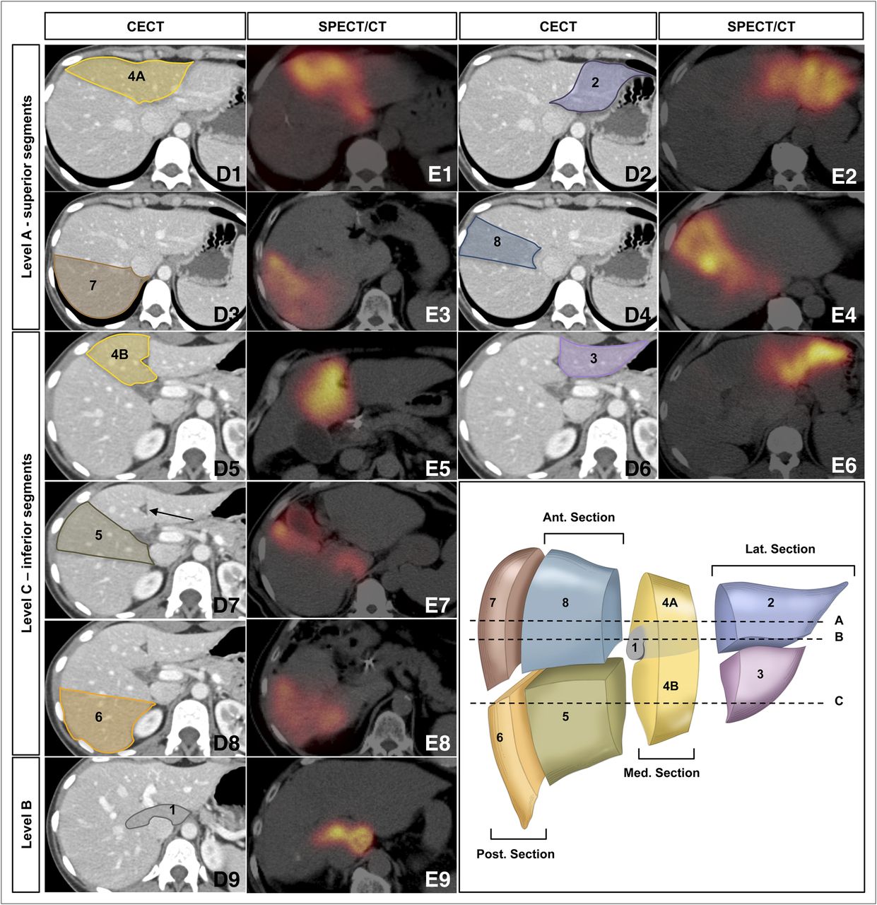
Segmental anatomy of liver: segments 1–8 of liver as depicted on contrast-enhanced CT (D1–D9) and on 99mTc-MAA hepatic perfusion SPECT/CT (E1–E9). Cross-sectional images at level A of anatomic illustration (bottom right) show superior segments of liver: segment 2 (parts D2 and E2 on contrast-enhanced CT and SPECT/CT, respectively, coded with purple), segment 4A (parts D1 and E1 on contrast-enhanced CT and SPECT/CT, respectively, coded with yellow), segment 7 (parts D3 and E3 on contrast-enhanced CT and SPECT/CT, respectively, coded with brown), and segment 8 (parts D4 and E4 on contrast-enhanced CT and SPECT/CT, respectively, coded with blue). Cross-sectional images at level C of anatomic illustration show inferior segments of liver: segment 3 (parts D6 and E6 on contrast-enhanced CT and SPECT/CT, respectively, coded with lilac), segment 4B (parts D5 and E5 on contrast-enhanced CT and SPECT/CT, respectively, coded with yellow), segment 5 (parts D7 and E7 on contrast-enhanced CT and SPECT/CT, respectively, coded with green), and segment 6 (parts D8 and E8 on contrast-enhanced CT and SPECT/CT, respectively, coded with orange). Cross-sectional images at level B of anatomic illustration show caudate lobe, segment 1 (parts D9 and E9 on contrast-enhanced CT and SPECT/CT, respectively, coded with gray). Arrow in part D7 points toward falciform ligament. Plane along this ligament separates lateral section of left hemiliver (segments 2 and 3, anatomic illustration) from medial section (segment 4) and can readily be recognized by triangular hypodense structure with rounded dense center. Falciform artery, extrahepatic branch of hepatic arterial vasculature, passes within ligamentum teres, free edge of falciform ligament. Color coding of this figure is used in Figures 2, 4, 6, and 7. CECT = contrast-enhanced CT.
Identification of the hepatic segments on diagnostic CT and MRI cross-sectional imaging uses landmarks to create 3 vertical–oblique planes and 1 horizontal plane intersecting the liver into segments 2–8. A vertical–oblique plane extending through the gallbladder fossa, middle hepatic vein, and inferior vena cava marks the midplane of the liver. The lateral section and the medial section of the left hemiliver are divided by a plane through the falciform ligament projecting on the path of the left hepatic vein. This plane is delineated on the liver surface and can clearly be identified on cross-sectional imaging (Fig. 1D7, arrow). The anterior and posterior sections of the right hemiliver are divided by a vertical–oblique plane projecting on the path of the right hepatic vein.
A horizontal plane intersecting the liver at the level of the right and left portal veins separates the superior and inferior segments of each section, segments 2 and 3 of the lateral section, segments 4A and 4B of the medial section, segments 8 and 5 of the anterior section, and segments 7 and 6 of the posterior section. The anterior-section segments are not labeled with consecutive numerals because the liver segments are numbered in a clockwise manner when facing the anterior surface of the liver, with segment 2 being the most superior lateral segment.
Segment 1, the caudate lobe, is an independent segment and may be supplied by the right hepatic artery (RHA), the left hepatic artery (LHA), or both (15). On cross-sectional imaging the caudate lobe is identified by its borders with the inferior vena cava and the porta hepatis (Figs. 1D9 and 1E9). The liver segments as identified on CT or MRI therefore match but are not identical to the anatomic liver segments.
Identifying the hepatic segments perfused with 99mTc-MAA on SPECT/CT is important but may be challenging in the absence of intravenous contrast medium, particularly if the patient had prior wedge surgical resections or if the distribution of the MAA particles is heterogeneous or geographic. A heterogeneous distribution of the 99mTc-MAA particles can be encountered under the following circumstances: presence of necrotic lesions, prior TACE treatments or bland embolizations with pruning of the distal arterial branches, invasion of the tumor into the portal triad with obstruction of segmental and subsegmental hepatic arteries (especially in primary malignancies of the liver such as central cholangiocarcinoma), aggregation of the 99mTc-MAA particles, or preferential flow dynamics to a certain part of the liver. Figure 1 demonstrates each of the liver segments on 99mTc-MAA hepatic perfusion SPECT/CT, along with contrast-enhanced CT images and anatomic illustration for orientation.
STANDARD AND NORMAL-VARIANT HEPATIC ARTERIAL ANATOMY ON ANGIOGRAPHY AND RESULTANT PERFUSION ON SPECT/CT
In the most common standard hepatic arterial anatomy, the common hepatic artery (CHA) originates from the celiac trunk, gives rise to the gastroduodenal artery (GDA), and continues as the proper hepatic artery (PHA) toward the porta hepatis, where it divides into the RHA and the LHA. Each of the hepatic arteries gives rise to segmental hepatic arteries to each segment of the liver. There are interhemilivers communicating arcades between the LHA and the RHA.
The middle hepatic artery (MHA) is not considered an anatomic variation but rather another type of standard anatomy and may arise from the RHA or from the PHA to provide a blood supply to segment 4 (15). Figure 2 illustrates a standard anatomy with the MHA emerging from the RHA on anatomic illustrations (Figs. 2A and 2C) and on digital subtraction angiography (DSA) (Figs. 2B, 2D, 2E, and 2F).
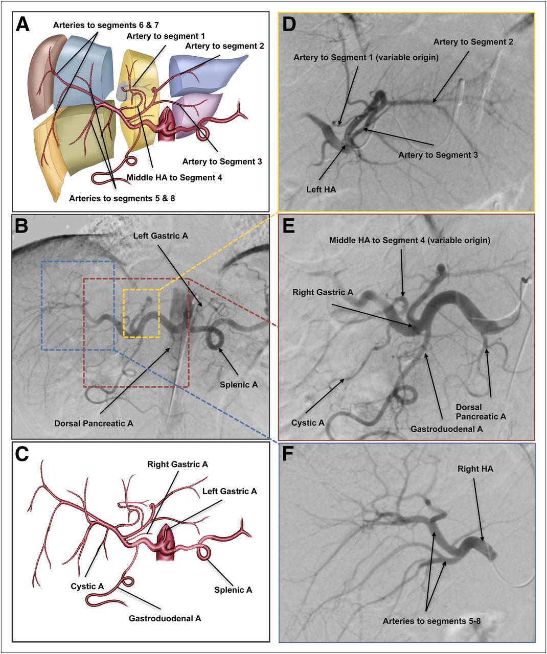
Standard hepatic arterial anatomy and important mesenteric vessels from celiac axis. (A) Anatomic illustration showing type of standard anatomy with MHA emerging from RHA and hepatic arteries to liver segments. MHA, regardless of its origin, will deliver blood supply to segment 4. (B) DSA of celiac axis injection. (C) Anatomic illustration introducing important players in liver radioembolization: RGA, LGA, GDA, and cystic artery (also shown in E, DSA image). (D) LHA selective injection delineating yellow dashed region in B. (E) CHA selective injection delineating red dashed region in B. (F) RHA selective injection delineating blue dashed region in B. In presence of MHA, LHA will deliver blood supply to lateral section of left hemiliver (A and D). RHA bifurcates to hepatic artery to anterior section (segments 5 and 8) and to hepatic artery to posterior section (segments 6 and 7) (A and F). Arterial blood supply to segment 1 is variable and can originate from LHA, RHA, or both. In this example of standard anatomy, LHA perfuses segment 1 (A and D). A and C are simplified anatomic illustrations of arterial anatomy and are not meant to be identical to angiographic images but rather to convey basic principles. A = artery; HA = hepatic artery.
Variations from the normal hepatic arterial vasculature are common and can be encountered in 40% of patients, with various classification systems described in the anatomic and surgical literature (Fig. 3). The variations typically involve a replaced artery, which is a vessel that substitutes for the typical vessel but emerges from a different vascular territory, or an accessory vessel, which is a vessel additional to the standard vasculature. Based on the original classification of Michel, there are 10 anatomic variations of the main hepatic vasculature, with type 1 being the standard anatomy (16). Most variations will affect radioembolization treatment planning. One may encounter unique arterial patterns not included in this classification.

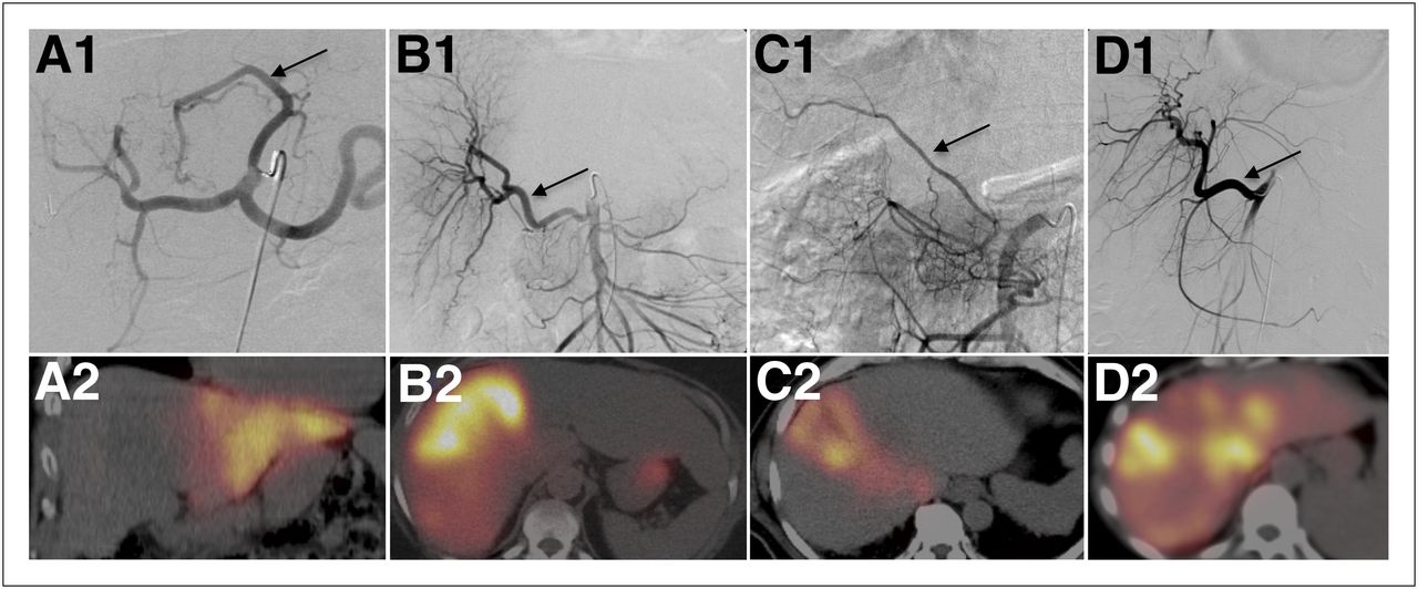
Normal variants of hepatic arterial vasculature and resultant perfusion on SPECT/CT. (A1 and A2) Replaced LHA from LGA (arrow in A1), known as Michel type 2 variant. Selective injection of 99mTc-MAA to this vessel revealed perfusion of lateral section (segments 2 and 3) of liver (A2). In this scenario, MHA from RHA territory will deliver blood supply to segment 4. (B1 and B2) Replaced RHA from SMA, Michel type 3, (arrow in B1) perfusing right hemiliver (B2). Activity seen in stomach is free 99mTc-pertechnetate uptake in gastric mucosa. (C1 and C2) Accessory RHA from SMA, Michel type 6 (arrow in C1). Selective injection of 99mTc-MAA to this vessel revealed perfusion to anterior section of right hemiliver (segments 5 and 8, C2). (D1 and D2) Replaced CHA from SMA, Michel type 9 (arrow in D1). Selective injection of 99mTc-MAA to this vessel revealed perfusion of entire liver (D2).
The type 2 variant consists of a replaced LHA arising from the left gastric artery (LGA), which may also be referred to as the gastrohepatic trunk (Figs. 3A1 and 3A2). This variant frequently has branches to the stomach, esophagus, and diaphragm (phrenic arteries). Detection of these branches is important, as they need to be excluded from the treated arterial territory either by placing the microcatheter beyond the takeoff of these vessels or by embolization to prevent nontargeted radioembolization of the distal esophagus or stomach.
The type 3 variant describes a replaced RHA from the SMA (Figs. 3B1 and 3B2). With type 2 or 3 variants, the replaced vessel may or may not deliver a blood supply to the medial section, segment 4 of the liver (Fig. 4). The type 4 variant consists of a replaced LHA from the LGA and a replaced RHA from the SMA. The type 5 variant consists of an accessory LHA emerging from the LGA. The type 6 variant consists of an accessory RHA from the SMA, which provides a blood supply to segments 5 and 8 (Figs. 3C1, 3C2, and 4). The type 7 variant is the coexistence of an accessory LHA and an accessory RHA. The type 8 variant consists of a replaced LHA originating from the LGA and an accessory RHA from the SMA or vice versa. The type 9 variant consists of a replaced CHA from the SMA (Figs. 3D1 and 3D2). The type 10 variant consists of a replaced CHA from the LGA.

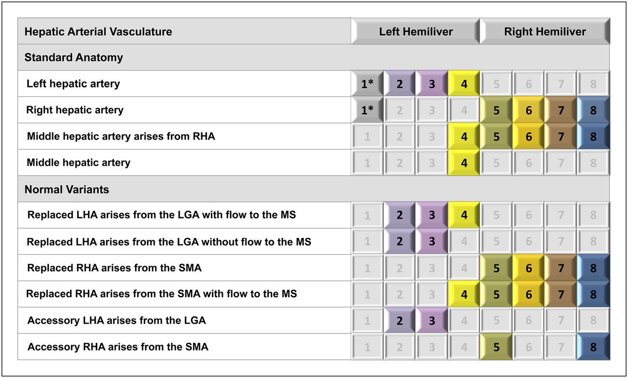
Standard and variant hepatic arterial anatomy and resultant segmental perfusion of liver. Pattern of hepatic arterial vasculature predicts segments of liver to be perfused. Common variant types based on Michel classification included in this table are type 2 (replaced LHA from LGA), type 3 (replaced RHA from SMA), type 5 (accessory LHA from LGA), and type 6 (accessory RHA from SMA). *Origin of hepatic artery to segment 1 (caudate lobe) is variable and may emerge from RHA, LHA, or both. MS = medial section of left hemiliver.
Other patterns not described in the original Michel classification have been reported in a large series of surgical, angiographic, and imaging reviews of the hepatic arterial anatomy, including a direct origin of the CHA from the aorta and a replaced PHA or CHA from the SMA with or without an accessory LHA from the LGA (17,18). The most common anatomic variants have a predictable perfusion pattern to the liver segments (Fig. 4). This knowledge is valuable in planning liver radioembolization.
VASCULAR MAPPING AND ARTERIAL EMBOLIZATION
The endovascular procedure performed by means of interventional radiology has 4 aims. The first is delineation of the mesenteric and hepatic arterial blood supply to plan the treatment strategy and particularly to identify any variant anatomy that may require separate treatment sessions (e.g., an accessory RHA emerging from the SMA, and a RHA emerging from the celiac axis in the case of a tumor involving the anterior and posterior sections of the liver). The second aim is prophylactic embolization, if indicated, of selected vessels perfusing gastrointestinal organs, typically the GDA and the right gastric artery (RGA). The third aim is detection and embolization of additional extrahepatic vessels emerging from the hepatic vasculature in the intended vascular territory to be treated to prevent nontargeted embolization. The fourth aim is injection of the 99mTc-MAA particles to vascular territories to be treated in order to delineate the flow dynamics and calculate the fraction of particles shunted to the lungs.
A different approach to angiographic vascular mapping is consolidation, which aims to eliminate the variant arteries and to redirect the arterial inflow to a major vessel for simplified and safer 90Y-microsphere administration. This approach is accomplished by selective embolization of competing arteries and, if performed, should be done before 99mTc-MAA infusion (19).
Vascular mapping includes a diagnostic portion and an interventional portion. The diagnostic portion of vascular mapping includes DSA of the celiac axis and SMA with optional additional aortography as needed. DSA of the SMA or celiac axis with a delayed venous phase is performed to assess the patency of the portal vein. Portal vein thrombosis is not a contraindication to treatment but should be taken into consideration in the initial clinical assessment. Selective DSA of the CHA and the PHA followed by selective angiography of the RHA, LHA, and, if present, MHA will further delineate the vascular anatomy. Selective DSA of additional relevant branches and of extrahepatic branches arising from the hepatic arterial vasculature is performed as described in the following sections. The interventional portion of the procedure consists of embolization of specific arteries to maximize targeted therapy and to prevent nontargeted radioembolization.
The use of CT (also known as cone-beam CT) during intraarterial contrast injection in the angiography suite can be helpful to identify extrahepatic shunting and to delineate more precisely the part of the liver perfused from the selective microcatheter injection. CT can be used as the main imaging modality during the procedure, with the advantage of 3-dimensional imaging of the upper abdomen, or can be used as a problem-solving tool only. Indications for using this tool include a complicated arterial vasculature (e.g., gastrohepatic trunk with numerous branches to upper abdominal and lower thoracic organs), the need to identify parasitizing vessels, and multisegmental liver disease whose blood supply originates from multiple vascular territories.
It has been postulated that dynamic CT acquisitions during arterial injection will help with arterial consolidation as a preparation for radioembolization. The cross-sectional imaging may guide planned embolization to redirect blood flow to the tumors by opening intrahepatic collateral pathways (19).
EXTRAHEPATIC BRANCHES ARISING FROM THE HEPATIC ARTERIAL VASCULATURE
Identifying extrahepatic branches that arise from the hepatic arteries is critical to preventing nontargeted infusion of microspheres to other organs. Prophylactic transcatheter embolization of the RGA and the GDA is commonly performed during the initial angiogram, particularly if their origin is near the planned microcatheter position for 90Y-microsphere infusion. Detailed interrogation before embolization is mandatory to make certain that hepatic arteries do not originate from those vessels (e.g., accessory RHA from the GDA). Unintended embolization of the GDA in the case of this specific anatomy may block access to the hepatic vascular territory needed for treatment.
The dorsal pancreatic artery (Figs. 2B and 2E), the main vessel to the neck and proximal body of the pancreas, usually emerges from the proximal splenic or celiac axis (15). In selective 90Y-microsphere infusions, the dorsal pancreatic artery usually is not a source of extrahepatic 99mTc-MAA activity unless a variable origin is encountered, such as from the CHA (20). Pancreatitis will likely occur if there is nontargeted radioembolization of this vessel.
The RGA can have a variable origin, typically from the CHA or PHA (Figs. 2B and 2E), but can emerge from the LHA or GDA. 99mTc-MAA activity seen along the lesser curvature of the stomach should raise the possibility of the RGA emerging from the injected vascular territory. If the territory planned for treatment mandates the infusion of 90Y-microspheres proximal to the origin of the RGA, it should first be embolized to prevent gastritis, ulceration, and potential gastrointestinal bleeding.
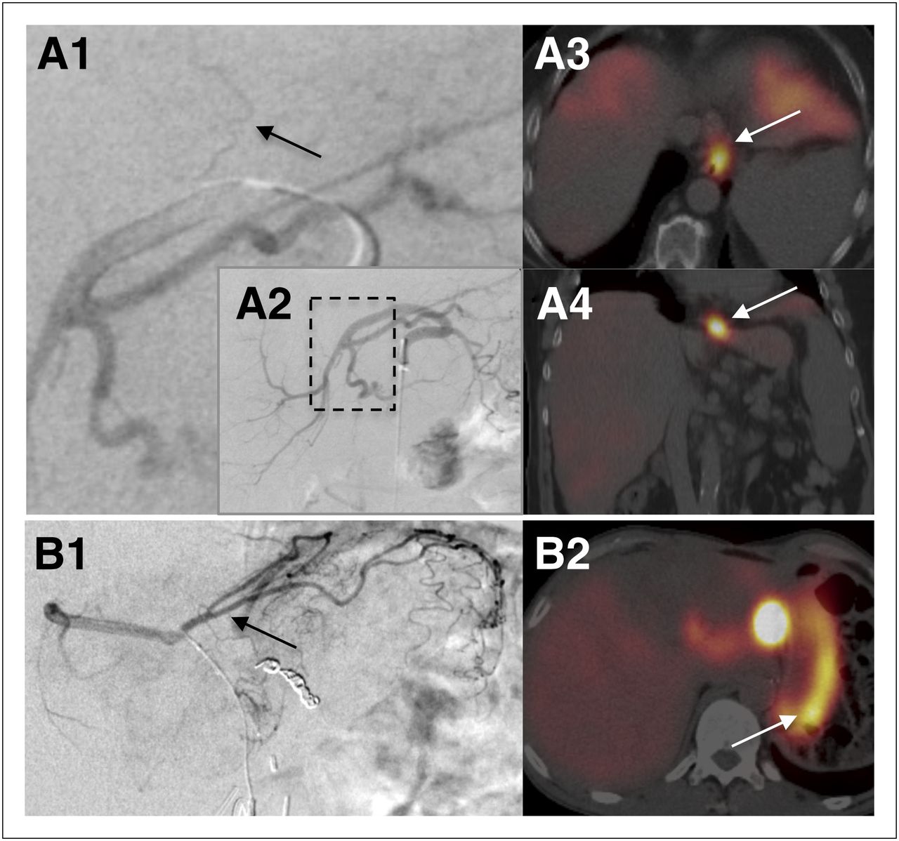
In addition to the previously described gastric, esophageal, and phrenic tributaries from the gastrohepatic trunk, which may be a source for extrahepatic activity in the stomach, esophagus, and diaphragm, respectively (Fig. 5), the LHA may give rise to a falciform artery. A falciform artery passes through the ligamentum teres, the free edge of the falciform ligament, to perfuse the anterior abdominal wall in the supraumbilical region (Fig. 6). The falciform artery may originate from the LHA or the MHA (15). In the case of a falciform artery, the 99mTc-MAA activity may be seen tracking from the anterior inferior aspect of the left hemiliver toward the supraumbilical skin and subcutaneous fat crossing the linea alba at midline. On the basis of case reports of infusion of 90Y-microspheres into the falciform artery during liver radioembolization, there is a potential risk of supraumbilical pain or a burning sensation and radiation dermatitis of the skin in nontargeted embolization of this artery (21,22). The interventional radiologist may decide to prophylactically embolize the falciform artery before 90Y-microsphere infusion to avoid this complication. There is debate in the literature about the need to pursue this intervention in every patient with supraumbilical activity on 99mTc-MAA hepatic perfusion imaging, as the associated complications are rare and typically do not result in severe morbidity (22,23). If the artery is too small and tortuous to catheterize for embolization and is included in the vascular territory to be treated, some experts recommend using cold-induced vasoconstriction by applying ice bags over the supraumbilical region during 90Y-microsphere administration to decrease the blood flow to further reduce the risk of any complications. Extrahepatic perfusion of 99mTc-MAA particles via the falciform ligament is not considered a contraindication to treatment with 90Y-microspheres.

Sites of extrahepatic perfusion from gastrohepatic trunk on SPECT/CT and corresponding vascular anatomy. (A1 and A2) DSA image of superselective contrast injection into replaced LHA, demonstrating small esophageal branch (arrow) oriented vertically toward distal esophagus. A1 is magnified image of boxed region in A2, which is selective injection to proximal replaced LHA and is presented for orientation. (A3 and A4) 99mTc-MAA activity in axial and coronal SPECT/CT images, respectively, indicating that distal esophagus was perfused by injected vascular territory. (B1) DSA image from different patient with anatomic variant of gastrohepatic trunk demonstrating gastric (arrow), hepatic, and phrenic branches. (B2) axial SPECT/CT image from 99mTc-MAA hepatic perfusion study showing extrahepatic perfusion in gastric wall.

Extrahepatic perfusion via falciform artery. At top left is anatomic illustration showing falciform artery emerging from hepatic artery to segment 4 of liver in patient with standard arterial anatomy. (A1) Selective DSA of LHA demonstrating falciform artery (solid arrows) crossing medially and inferiorly along anatomic location of ligamentum teres and then turning toward midline beyond boundaries of liver. GDA was prophylactically embolized with metallic coils (dashed arrow). (A2) Selective DSA of LHA in left anterior oblique projection in same patient, showing anterior course of falciform artery (solid arrow). (A3 and A4) Sagittal reconstructions of contrast-enhanced CT showing course of falciform artery from anterior edge of liver to subcutaneous fat superior to umbilicus (arrows). (A5) Reconstructed sagittal image from 99mTc-MAA SPECT/CT demonstrating extrahepatic activity along course of falciform artery, skin, and subcutaneous fat of supraumbilical region (arrow). A = artery.
If the LGA is perfused with 99mTc-MAA, the activity typically will be seen in the gastric fundus and cardia and along the lesser curvature of the stomach.
From the RHA vascular territory, the extrahepatic vessels typically encountered are the cystic artery and the supraduodenal artery, delivering blood supply to the gallbladder and the proximal two thirds of the duodenum, respectively (15). The origin of these vessels is variable and includes the left hepatic, common hepatic, or gastroduodenal arteries. 99mTc-MAA activity will be seen outlining the gallbladder wall in the case of a perfused cystic artery or may be seen as more focal and typically in the region of the first and second parts of the duodenum in the case of a supraduodenal artery (Fig. 7). If there is clinical concern about possible radiation cholecystitis, this concern may be addressed with pretreatment embolization of the cystic artery. However, radiation cholecystitis can usually be managed conservatively, and many interventional radiologists do not embolize the cystic artery. Duodenal activity should be interrogated, as the risks of radiation-induced duodenitis, frank ulceration, and upper gastrointestinal bleeding may be significant.

Extrahepatic perfusion via supraduodenal artery. At bottom left is anatomic illustration showing supraduodenal artery emerging from RHA. (A1) DSA image of selective injection of contrast medium to RHA demonstrating supraduodenal artery (arrow) crossing medially and inferiorly. (A2 and A3) Axial and coronal images from 99mTc-MAA SPECT/CT demonstrating extrahepatic 99mTc-MAA activity at border of parts 1 and 2 of duodenum (solid arrows). GDA was prophylactically embolized with metallic coils (dashed arrow). (A4) Coronal image from contrast-enhanced CT of same patient for reference, with arrow pointing toward location of 99mTc-MAA activity in duodenum. A = artery.
UNUSUAL SITES OF 99MTC-MAA ACTIVITY DETECTED ON PERFUSION STUDIES
SPECT/CT images may reveal unusual sites of 99mTc-MAA activity within and outside the liver. Comparing the SPECT/CT images with the contrast-enhanced CT or MR images will enable better anatomic localization of the findings. A tumor thrombus of the portal vein or the hepatic vein, more commonly seen with primary hepatic malignancies such as HCC, can accumulate 99mTc-MAA activity (Figs. 8A1 and 8A2). A portal tumor thrombus may be seen on SPECT/CT as a continuous area of activity extending from the tumoral lesion in the liver parenchyma into the portal system. This finding usually correlates with direct invasion of the portal vein by the primary tumor on contrast-enhanced cross-sectional imaging, suggesting that the tumor thrombus is supplied with blood through neovascularization from the hepatic arteries, as is the tumor itself. A hepatic vein tumor thrombus in patients with HCC is associated with increased shunting to the lungs, compared with patients without hepatic vein involvement. The increased shunting to the lungs may limit or preclude treatment (24).

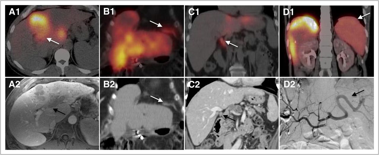
Unusual sites of 99mTc-MAA activity on SPECT/CT hepatic perfusion studies. (A1) Fused SPECT/CT image showing 99mTc-MAA activity in segments 4 and 1 in patient with HCC. Activity in segment 4 is seen extending into portal vein (arrow), correlating with tumor thrombus on contrast-enhanced MRI T1-weighted image (A2, arrow). (B1 and B2) Fused SPECT/CT and CT coronal images of different patient showing 99mTc-MAA activity in left hemidiaphragm (arrows). Angiographic images showed that left phrenic artery emerges from LHA, which was injected with 99mTc-MAA. (C1) Fused SPECT/CT coronal image showing 99mTc-MAA activity in paracaval lymph nodes (arrow). (C2) Coronal reconstruction of contrast-enhanced CT of same patient demonstrating abnormal lymph node (arrow). Second lymph node was identified in adjacent slide. Angiographic images showed extrahepatic branch emerging from PHA perfusing this anatomic region. (D1) Fused SPECT/CT of different patient showing 99mTc-MAA activity in spleen (arrow). 99mTc-MAA particles were injected to a replaced RHA. (D2) Angiographic image demonstrating retrograde flow from replaced RHA to celiac axis territory and splenic artery in this patient after right portal vein embolization and multiple transarterial chemoembolizations.
99mTc-MAA activity in the diaphragm can be seen if phrenic tributaries emerge from the injected vascular territory, typically from the LHA or the gastrohepatic trunk (Figs. 8B1 and 8B2). The hepatic arteries can give rise to recruited branches to sites of local extension of the disease. Although uncommon, 99mTc-MAA activity in advanced disease can be seen in metastatic locoregional lymph nodes that are supplied blood through neovascularization from the hepatic arteries (Figs. 8C1 and 8C2). Splenic activity can be seen in cases of retrograde flow of 99mTc-MAA particles to the splenic artery or in cases of altered flow dynamics, typically in patients who were previously treated with TACE or bland embolization in which blood flow from the hepatic arteries is directed to the spleen (Figs. 8D1 and 8D2).
TREATMENT PLANNING
Vascular mapping includes a diagnostic portion (a detailed angiographic interrogation) and an interventional portion (isolation of the hepatic arterial vasculature to be treated). The decision on the treatment strategy—whole-liver treatment versus staged hemiliver treatment versus radiation segmentectomy—is based on the diagnostic cross-sectional and angiographic findings and on the interventional results (25). Radiation segmentectomy is selective treatment to 1 or 2 segments of the liver or part of a segment (26). The angiographic procedure will also mandate the way in which the 99mTc-MAA dose is injected: single injection of the entire dose to the PHA versus splitting the dose to separately inject the arteries to each hemiliver, to a certain segmental artery, or to accessory arteries. The diagnostic findings, the interventions performed, the method of 99mTc-MAA injection, and the details of treatment planning are important for accurate interpretation of the 99mTc-MAA hepatic perfusion findings.
99MTC-MAA HEPATIC PERFUSION IMAGING PROTOCOL
Before injection, the 99mTc-MAA syringe should be gently tilted to agitate and resuspend the 99mTc-MAA particles. This step will minimize clumping of the particles, which might cause an inhomogeneous distribution. The injection should be done using meticulous sterile technique and should proceed at a rate of a few minutes to avoid streaming. Steps to avoid injecting air into the arterial system should be taken. The adult dose is typically 185 MBq (5 mCi) suspended in normal saline. If the whole liver is being evaluated for treatment, the usual dose injected into the right and left hemilivers is approximately 111 mBq (3 mCi) and 74 mBq (2 mCi), respectively. If the patient underwent a prior partial resection or portal vein embolization with subsequent hypertrophy of the contralateral hemiliver, the split doses should be adjusted according to the relative size of each part of the liver to be injected.
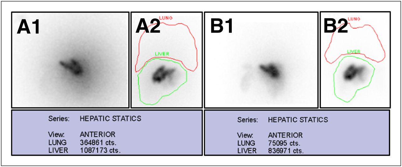
Typically, anterior static images or anterior and posterior static images are acquired to calculate the fraction of 99mTc-MAA shunted to the lungs. A single region of interest is drawn around both lungs, and an additional region of interest is drawn around the liver (Fig. 9). The percentage of shunting to the lungs is estimated by the ratio of counts in the lungs to the sum of counts in the lungs and liver, multiplied by 100. If anterior and posterior views are obtained, the geometric mean of the counts in the lung and liver regions of interest would give the most accurate results.

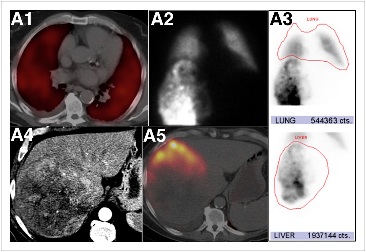
Excessive pulmonary 99mTc-MAA shunting in patient with HCC. (A1) Fused SPECT/CT axial image of chest showing marked diffuse 99mTc-MAA activity in both lungs, indicating shunted MAA particles from arterial hepatic circulation to lungs. (A2) Anterior planar static image of chest and upper abdomen after 99mTc-MAA injection to RHA, showing heterogeneous distribution of 99mTc-MAA activity in right hemiliver and diffuse activity in lungs. (A3) Regions of interest around lung and liver and counts in each region. Calculated lung shunting was 21.9%. (A4) Axial contrast-enhanced CT image in liver setup window showing large mass occupying most of right hemiliver. (A5) Fused SPECT/CT image of liver showing 99mTc-MAA activity in segment 5 but no appreciable activity in mass. 99mTc-MAA particles were shunted to lungs by direct arteriovenous connections within tumor neovasculature. High percentage of 99mTc-MAA particles that shunted to lungs precluded this patient from treatment with radioembolization.
With TheraSpheres, the upper limit of injected activity shunted to the lungs (percentage of shunting to the lungs times the planned therapeutic activity) is 610.5 mBq (16.5 mCi) (12). With SIR-Spheres, the activity should be adjusted to the percentage of lung shunting as follows: for less than a 10% shunt, a full amount of SIR-Spheres can be delivered; for 10%–15%, the amount should be reduced by 20%; for 15%–20%, the amount should be reduced by 40%; and for more than 20%, the administration of SIR-Spheres is contraindicated (5). These limitations are applied to prevent exceeding a maximum dose of 30 Gy to a 1-kg lung mass (7).
Activity in the thyroid gland, kidneys, and stomach due to the in vivo biodegradation of 99mTc-MAA particles in the liver and the presence of free 99mTc-pertechnetate in the systemic circulation should not be included in calculations of the percentage of lung shunting. In vivo biodegradation of 99mTc MAA is often significant because of the delay between the 99mTc-MAA injection and imaging. Uptake of free 99mTc-pertechnetate in the stomach should not be misinterpreted as an extrahepatic perfusion of 99mTc-MAA. Free 99mTc-pertechnetate is typically imaged as mildly increased activity outlining the entire gastric mucosa, whereas focal 99mTc-MAA activity in the stomach or an area of increased activity in the stomach wall is seen with unintended extrahepatic perfusion. In cases of unintended extrahepatic perfusion to the stomach, the degree of 99mTc-MAA activity may be variable depending on the flow dynamics in the gastric artery involved. Using recently made 99mTc-MAA with high labeling efficiency and minimizing the delay in imaging the patient after the endovascular procedure will reduce the amount of nonspecific background activity. Immobilization of the lower extremities after a femoral artery puncture is important to minimize the risk for bleeding, and therefore extra care should be used when transferring the patient to the SPECT/CT bed.
SPECT/CT VERSUS SPECT VERSUS PLANAR IMAGING
Anatomic localization of sites of 99mTc-MAA activity is greatly facilitated by the use of fused SPECT and CT images and facilitates a more confident interpretation of these complex studies. Foci of 99mTc-MAA abutting the liver parenchyma may be difficult to detect as extrahepatic sites of perfusion on planar imaging, especially in the presence of a nonhomogeneous hepatic distribution of 99mTc-MAA. SPECT/CT more accurately identifies sites of extrahepatic activity than does SPECT or planar imaging only.
Retrospective analysis of 90 hepatic perfusion studies of 76 patients with various types of cancers revealed sensitivities of 100%, 41%, and 32% and specificities of 98%, 98%, and 93% for SPECT/CT, SPECT, and planar imaging, respectively. The SPECT/CT findings affected management in 29% of patients (27). A similar prospective comparison between SPECT/CT with diagnostic contrast-enhanced CT, SPECT, and planar imaging of 68 examinations of patients with HCC demonstrated superior performance for SPECT/CT. The sensitivity and specificity for detection of gastrointestinal shunting were 100% and 94%, respectively, with SPECT/CT; 56% and 87%, respectively, with SPECT; and 25% and 87%, respectively, with planar imaging (28). The increased efficacy of SPECT/CT, compared with planar imaging, in detecting sites of extrahepatic activity was also demonstrated in a study that analyzed 136 hepatic perfusion examinations using 99mTc-MAA. Extrahepatic activity was identified at a higher rate with SPECT/CT (36.6% of cases) than with planar imaging only (5.7% of cases). In approximately 36% of the SPECT/CT studies, the findings had a potential impact on patient management (29).
The data in the literature support the use of SPECT/CT for accurate diagnosis of extrahepatic sites of 99mTc-MAA, with potential changes in treatment management and prevention of serious complications.
OPTIMIZATION OF THE IMAGING PROTOCOL IN CONCURRENT ADMINISTRATION OF 99MTC-MAA AND 90Y-MICROSPHERES
Three clinical scenarios warranting concurrent administration of 90Y-microspheres and 99mTc-MAA may be encountered. The first is related to an overlooked variant anatomy on the initial vascular mapping procedure, where the 99mTc-MAA perfused only part of liver that was intended to be treated. A typical example of this scenario is a tumor involving the left hemiliver, segments 2, 3, and 4, with a replaced LHA perfusing segments 2 and 3 and the MHA emerging from the RHA to segment 4. If the 99mTc-MAA was infused to the replaced LHA on the initial vascular mapping, then the dose that is needed to treat the lateral section, segments 2 and 3, can be calculated. However, the fraction shunted to the lungs by the tumor involving segment 4 still needs to be evaluated. In the second session, segment 4 can be evaluated by injection of 99mTc-MAA to the MHA, whereas the lateral sector can be treated by infusion of 90Y-microspheres to the replaced LHA. The second scenario is evidence of extrahepatic perfusion on the 99mTc-MAA hepatic perfusion scan that in retrospect can be identified on DSA imaging. An example of this scenario will be extrahepatic duodenal activity and a low fraction of lung shunting on a 99mTc-MAA study in which the 99mTc-MAA dose was injected separately to each hemiliver. In this case, coil embolization of the supraduodenal vessel with subsequent 99mTc-MAA infusion to the RHA and 90Y-microsphere infusion to the left hemiliver can be performed safely during the same interventional radiology procedure. The third scenario includes HCC involving both hemilivers and angiographic evidence of shunting to the lungs. In this case, only 1 hemiliver is assessed first with 99mTc-MAA. If the percentage of 99mTc-MAA shunted to the lungs by the first hemiliver is acceptable for treatment, this hemiliver is treated. At the treatment session, the second hemiliver is evaluated with 99mTc-MAA (20).
The interaction of the β− particles emitted during 90Y decay within the liver parenchyma induces bremsstrahlung radiation. Bremsstrahlung radiation has a broad spectrum of energies. The low-energy photons overlap the 99mTc-MAA energy window used for SPECT, and the high-energy photons may penetrate the septa of the low-energy collimator typically used. With concurrent administration of 90Y-microspheres and 99mTc-MAA, the interference of bremsstrahlung radiation will degrade the image quality of the 99mTc-MAA. It has previously been shown that the spectrum of 90Y bremsstrahlung radiation, as detected by the γ-camera detectors, differs with the type of collimator used (30). A medium-energy collimator, instead of a low-energy all-purpose collimator, will optimize imaging of the 140-keV photons of 99mTc-MAA by eliminating most of the higher-energy photons of the bremsstrahlung radiation. A low-energy high-resolution collimator can also be used (31). Narrowing the energy window to 10% will further reduce the amount of scattered bremsstrahlung photons reaching the detectors. Detection of scattered photons will falsely increase the number of counts in the lungs, thereby overestimating the percentage of lung shunting (Fig. 10).
Concurrent administration of 90Y-microspheres and 99mTc-MAA: optimizing the imaging protocol. This patient underwent radioembolization with 90Y-microspheres to right hemiliver and injection of 99mTc-MAA to left hemiliver. Static posterior (A1) and anterior (A2) images of liver using low-energy collimator showing high background activity caused by 90Y-induced bremsstrahlung radiation. Calculated percentage of 99mTc-MAA that shunted to lungs based on counts in regions of interest shown in anterior view, A2, was 25.1%. Static posterior (B1) and anterior (B2) images of liver using medium-energy collimator showing less background activity. Calculated percentage of 99mTc-MAA shunted to lungs based on counts in regions of interest shown in anterior view, B2, was 8.2%.
CONCLUSION
Endovascular mapping and conjoint 99mTc-MAA hepatic perfusion imaging comprise a pivotal step that precedes liver radioembolization with 90Y-loaded microspheres. This 2-part procedure is integrated into a multistep multidisciplinary treatment approach. A thorough understanding of the anatomy and technical aspects of the angiographic procedure is essential to accurately interpret hepatic perfusion imaging so that therapy can be optimized. Further reading is encouraged on the clinical aspects and dosimetry models of liver radioembolization to gain a complete overview of this unique treatment.
Acknowledgments
We acknowledge Vicki Friedman and Andrea Myles for their contribution in the creation of highly professional anatomic and medical illustrations to visually convey the concepts of this review.
Footnotes
Learning Objectives: On successful completion of this activity, participants should be able to describe (1) the rationale and the aims of conjoint endovascular mapping and 99mTc-macroaggregated albumin (99mTc-MAA) hepatic perfusion imaging before liver radioembolization; (2) how to integrate the information gathered during the angiographic procedure with the SPECT/CT hepatic perfusion study to generate an interpretation relevant to clinical management; (3) various sites of 99mTc-MAA activity outside the liver parenchyma and their potential origin in order to avoid nontargeted radioembolization; and (4) pitfalls in 99mTc-MAA hepatic perfusion imaging and how to avoid them.
Financial Disclosure: Dr. Darcy is a consultant/advisor for Angiodynamics and Boston Scientific, is a meeting participant/lecturer for W.L. Gore; and is involved in scientific studies/trials sponsored by Bard and W.L. Gore. Dr. Saad is a proctor for Sirtex Medical Ltd. The authors of this article have indicated no other relevant relationships that could be perceived as a real or apparent conflict of interest.
CME Credit: SNMMI is accredited by the Accreditation Council for Continuing Medical Education (ACCME) to sponsor continuing education for physicians. SNMMI designates each JNM continuing education article for a maximum of 2.0 AMA PRA Category 1 Credits. Physicians should claim only credit commensurate with the extent of their participation in the activity. For CE credit, participants can access this activity through the SNMMI Web site (http://www.snmmi.org/ce_online) through November 30, 2015.
- © 2012 by the Society of Nuclear Medicine and Molecular Imaging, Inc.
REFERENCES
- Received for publication July 19, 2012.
- Accepted for publication October 15, 2012.


Jump to section
- Article
- Abstract
- 90Y RADIONUCLIDE
- 90Y-MICROSPHERES AND 99MTC-MAA PARTICLES
- HISTORICAL PERSPECTIVE
- VASCULAR MAPPING AND 99MTC-MAA HEPATIC PERFUSION IMAGING
- LIVER SEGMENTAL ANATOMIC CONSIDERATIONS
- STANDARD AND NORMAL-VARIANT HEPATIC ARTERIAL ANATOMY ON ANGIOGRAPHY AND RESULTANT PERFUSION ON SPECT/CT
- VASCULAR MAPPING AND ARTERIAL EMBOLIZATION
- EXTRAHEPATIC BRANCHES ARISING FROM THE HEPATIC ARTERIAL VASCULATURE
- UNUSUAL SITES OF 99MTC-MAA ACTIVITY DETECTED ON PERFUSION STUDIES
- TREATMENT PLANNING
- 99MTC-MAA HEPATIC PERFUSION IMAGING PROTOCOL
- SPECT/CT VERSUS SPECT VERSUS PLANAR IMAGING
- OPTIMIZATION OF THE IMAGING PROTOCOL IN CONCURRENT ADMINISTRATION OF 99MTC-MAA AND 90Y-MICROSPHERES
- CONCLUSION
- Acknowledgments
- Footnotes
- REFERENCES
- Figures & Data
- Info & Metrics